
I liked the idea of using a smaller torch with my TIG welder, but for welding aluminium, it would need to be the water cooled WP20 to handle the current…. So I needed a water cooler / pump.
I though it would be a useful beginner project to weld one together out of aluminium.
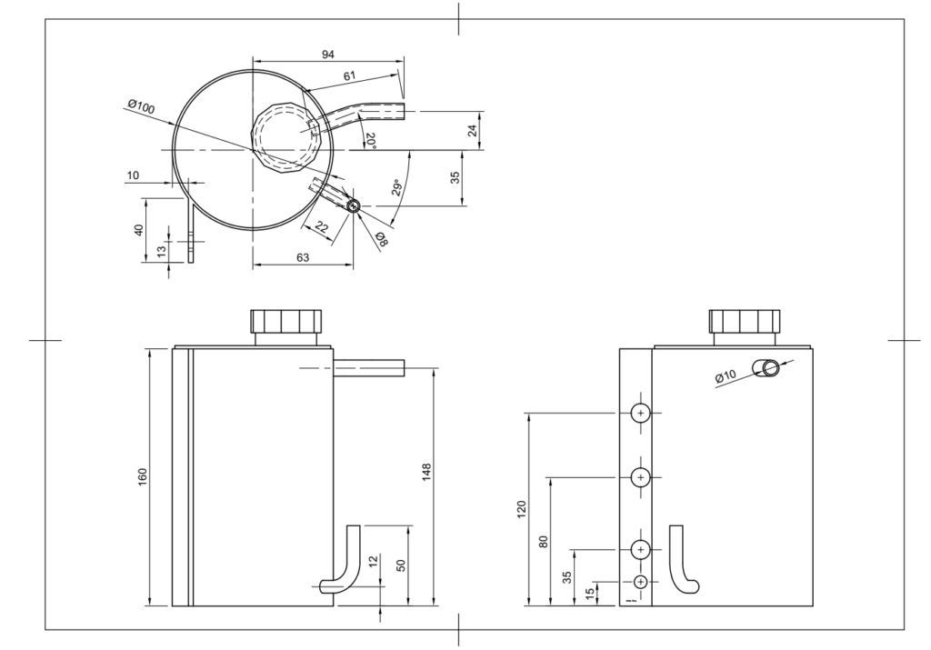
I had a length of ~100mm diameter aluminium tube that I thought could form the basis of the water tank, so I had a play around with Fusion360 and came up with the following dimensions, to suit the material I had available and a water cooled PC radiator.
This is a small, compact cooler. It was built using materials that I had available, as much for the challenge without a huge expectation that it would work. As it happens, it has worked very well for the fairly low duty cycle welding I’ve been doing as a hobbyist.
***Disclaimer!***
I am very much a beginner at TIG welding – There are images of amateurish welding which may cause distress to proper welders – viewer discretion advised! 😉
This was what I was trying to make:
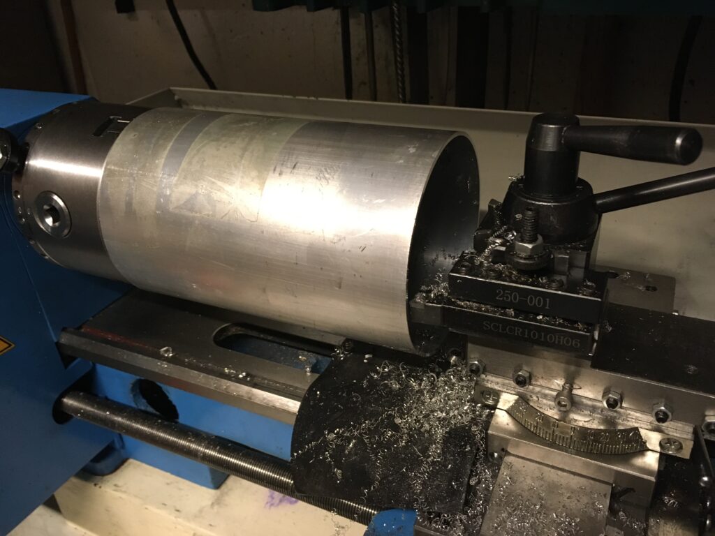
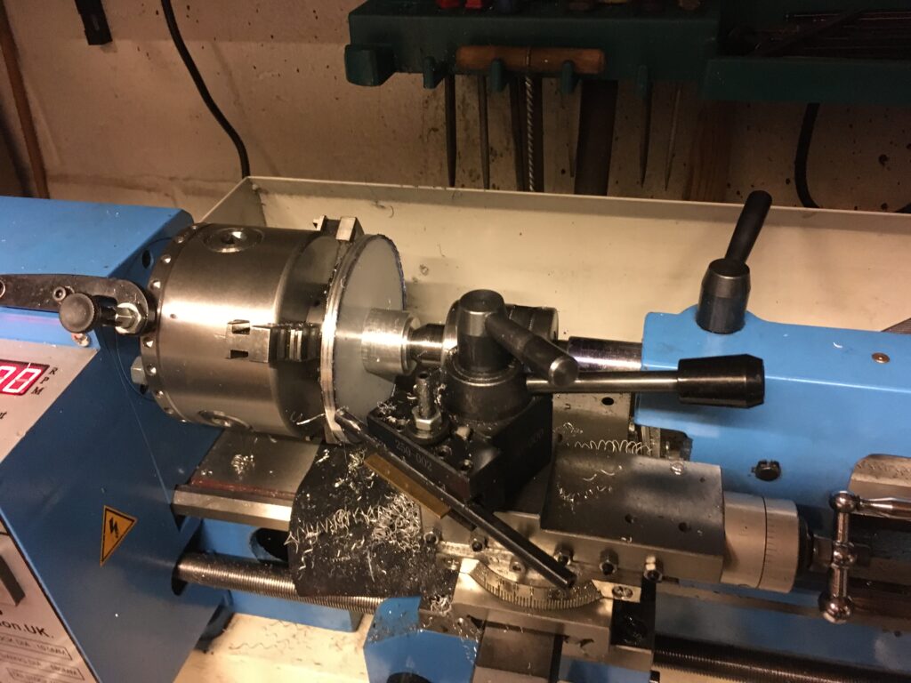
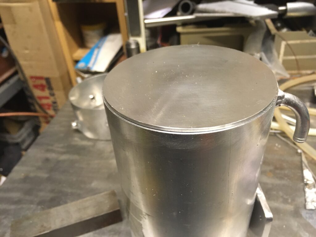
After sawing a length off the aluminium tube, the ends were trued up in the lathe very, very cautiously (there wasn’t much grip available from the chuck!).
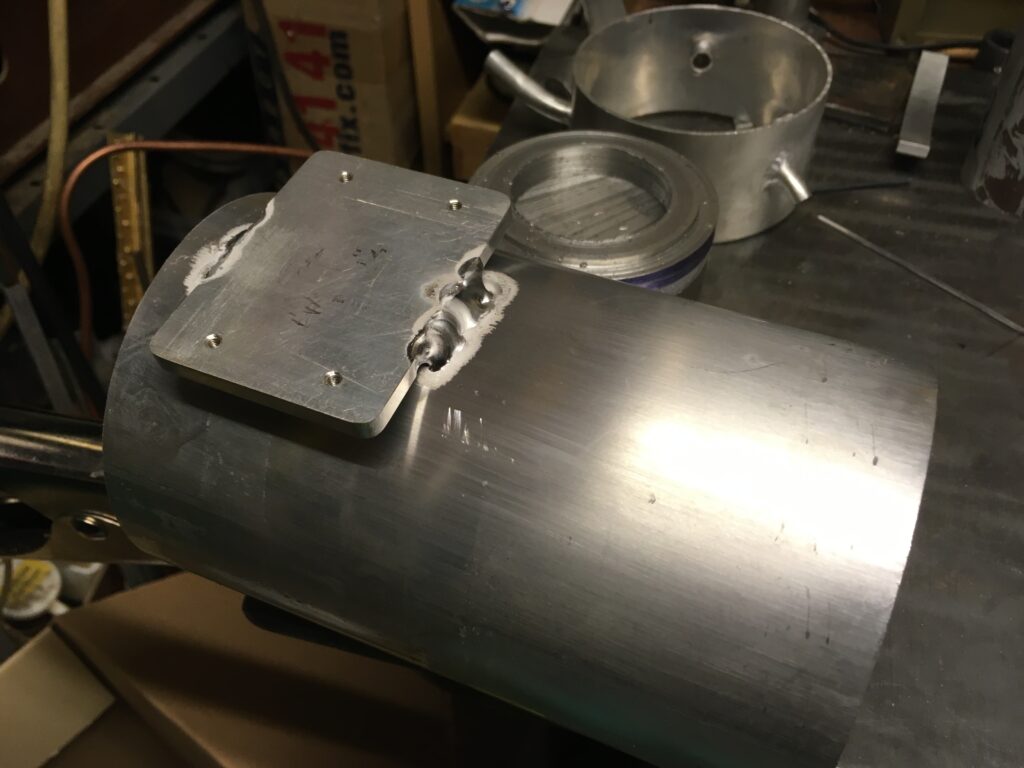
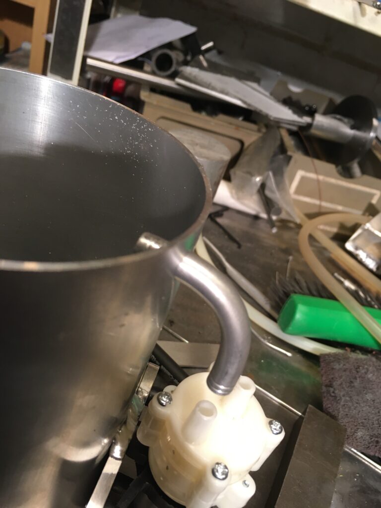
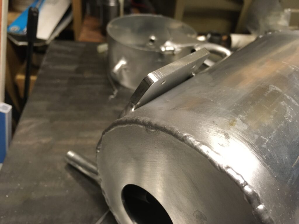
I welded a pad on the side of the tube to take a small 12V, 2 LPM circulating pump (from Amazon).
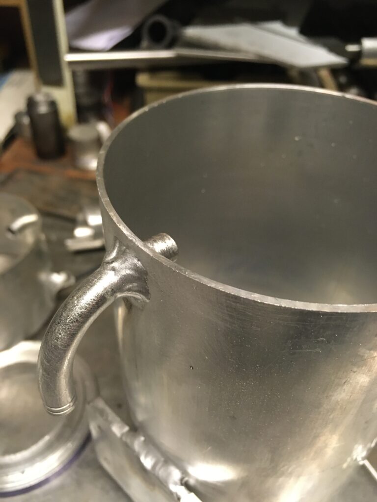
Then made some hose connections out of aluminium tube, bent them to suit and welded them into the tank:
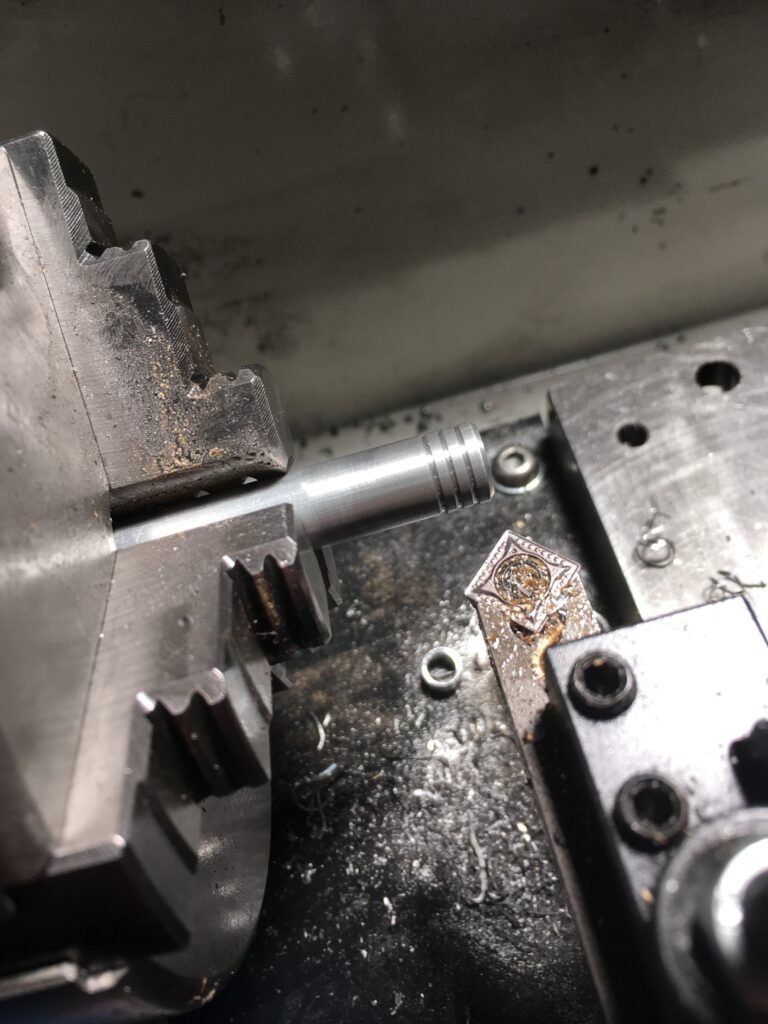
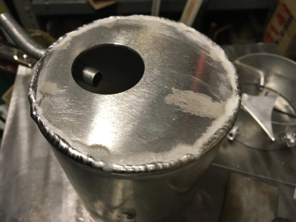
End caps were roughed out of aluminium sheet and trued up on the lathe using ‘pressure’ turning (the discs were held by being squeezed between a piece of bar in the chuck and another one sitting on the live centre). This allows the edges to be trued without having to make a hole in the discs.
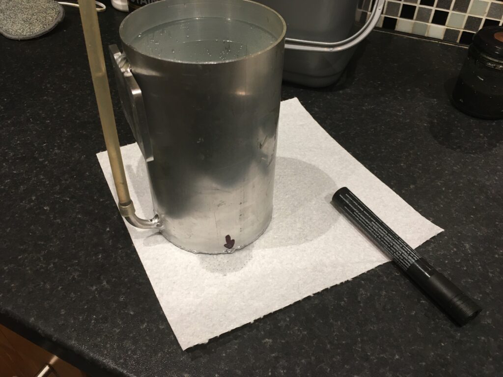
I could then weld the bottom on the tank and check for leaks.
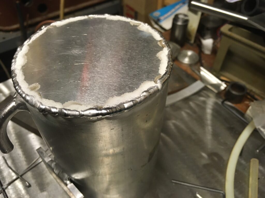
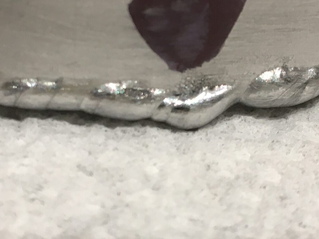
There was a leak…
It was obvious on close examination that I’d missed the edge. Running over it again was enough to seal it up
The top cover was welded on the same way after cutting a hole for the filler neck. The filler hole was positioned over the end of the return pipe, so that the flow would be visible when the filler cap was removed:
It didn’t look too bad after a quick wire brushing:
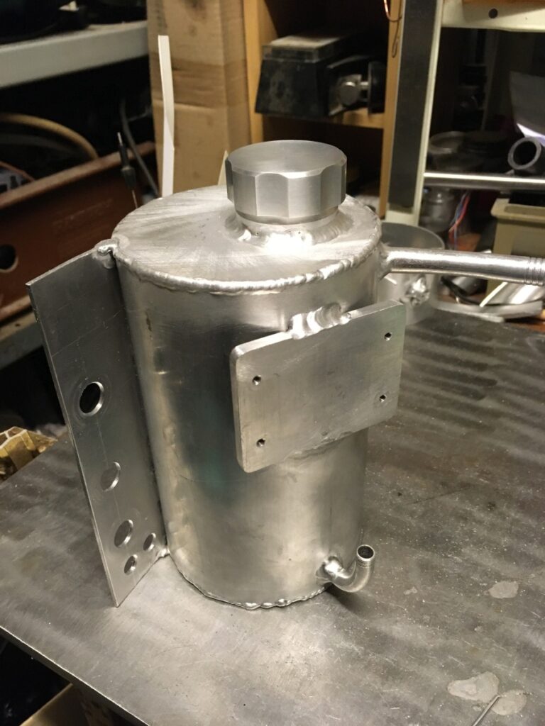
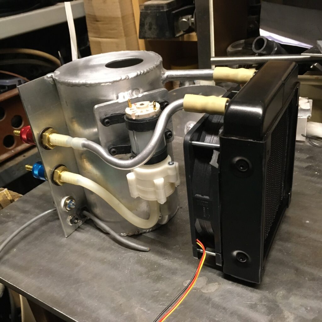
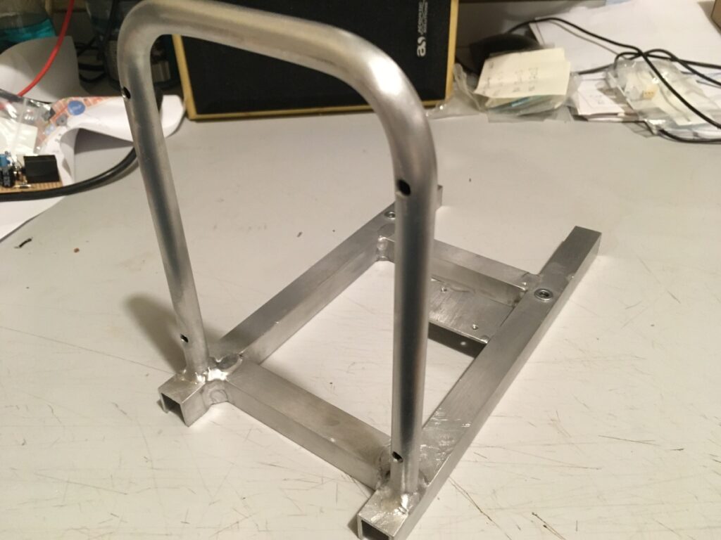
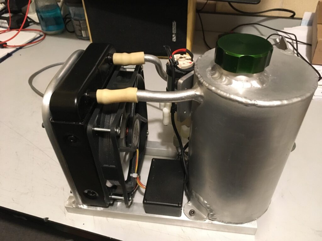
I connected up the various bits with rubber hose and worked out a mounting frame:
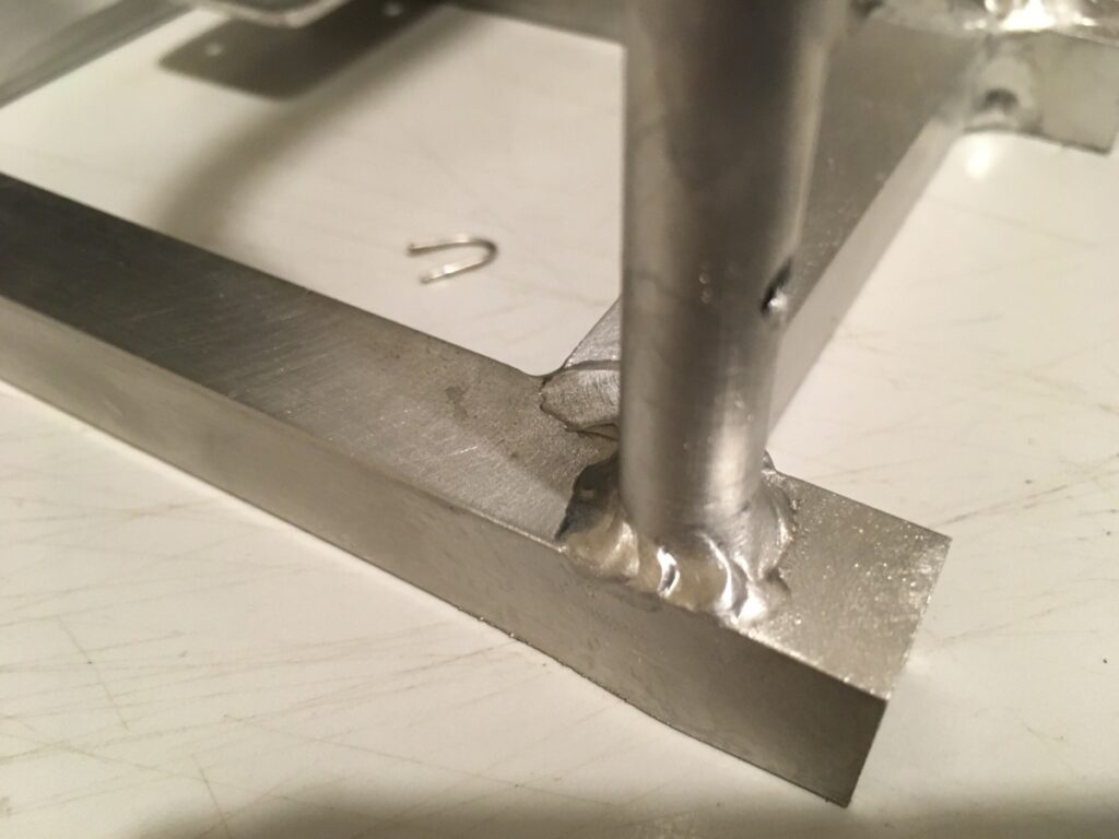
The framework was welded up from small alloy channel & tubing that I had around. It also included mountings for a small plastic box that would contain the control electronics.
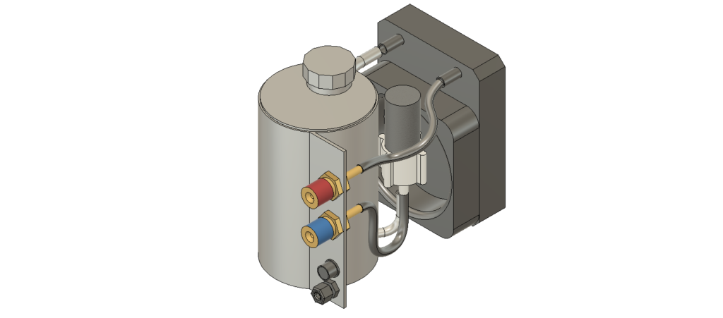
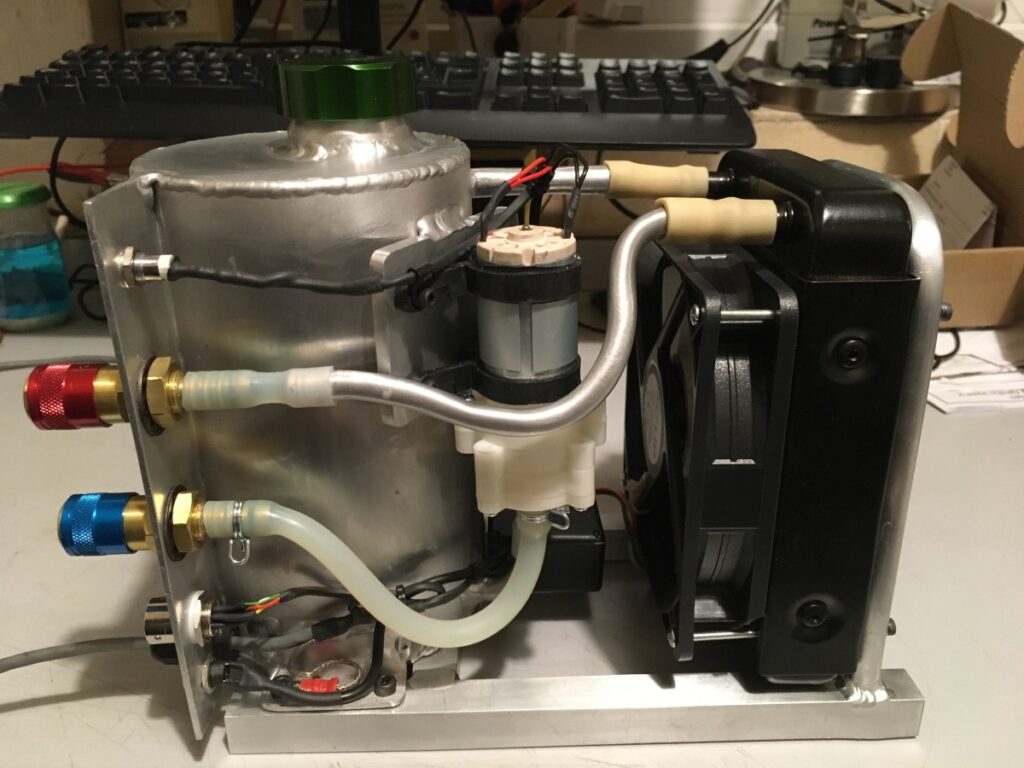
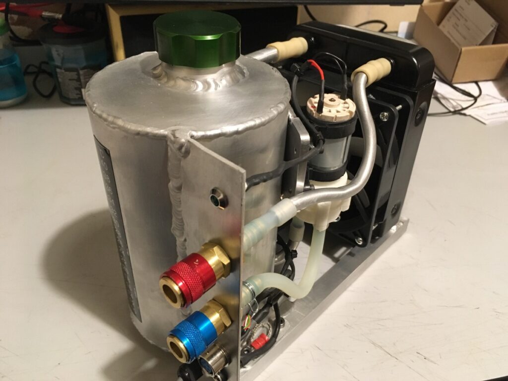
Once fully assembled, I thought it looked quite good! (I anodised the filler cap to try out my green dye.)
I had a few requirements for the control of the cooler:
- It shouldn’t be possible to weld unless the cooler was running
- The cooler should work with the torch button or the foot pedal
- Ideally, the cooler should start automatically when the torch button / pedal was pressed
- The cooler should run for a set period after the last weld before turning off
- I wanted to keep mains electricity away from the water / welding bit
To keep the cooler interchangeable between push button and foot pedal, and to try and keep the connections to the welder / torch as neat as possible, I decided to fit a control socket to the cooler that duplicated the one on the welder – that way, either the torch or the foot-pedal control could be plugged in. The connections for the amperage control pot in the pedal just run straight through to the welder socket, but the trigger contacts directly switch a relay inside the cooler. If the cooler has power, the relay closes another set of contacts that run to the trigger input on the welder – no power to the cooler = no trigger to the welder.
The trigger inputs from the torch also start a timer circuit that runs the water pump and cooling fan for about 15 minutes.
Every time the torch trigger is pressed, it resets this timer, so that the pump etc. runs continuously while welding, and for about 15 minutes afterwards. (This has proved entirely sufficient to prevent damage to the torch.)
The control is based on the 555 timer IC in a monostable circuit:
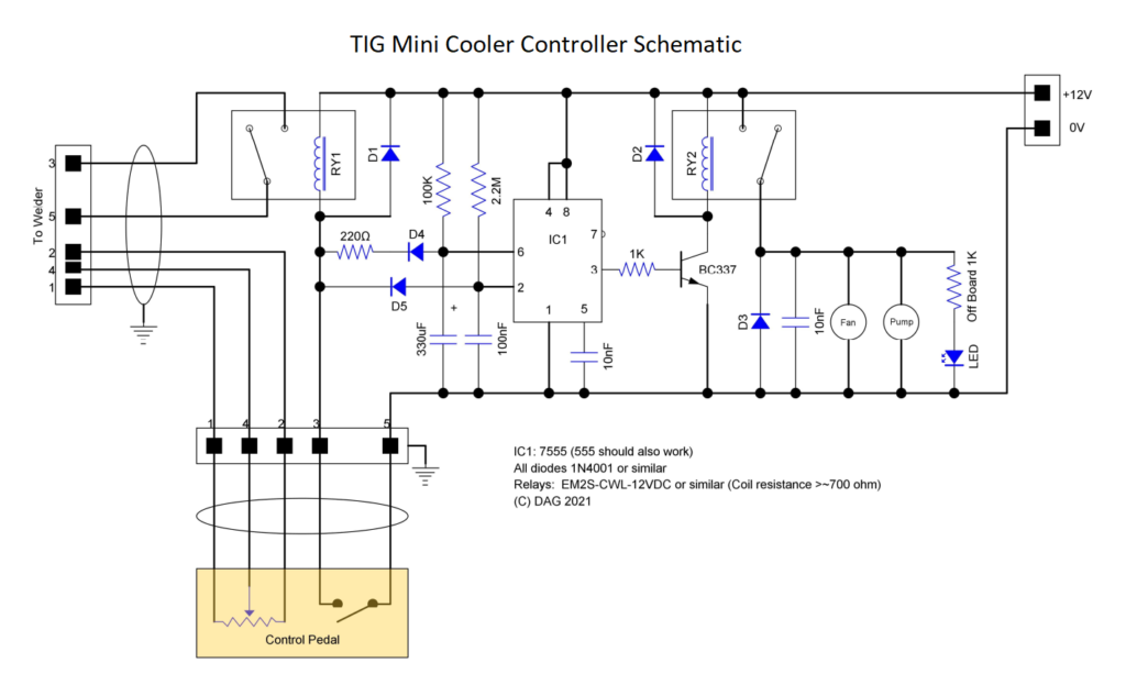
The run-on time is set by the 100k resistor an 330µF capacitor. Every time the switch in the torch / pedal is closed, the timing capacitor is discharged via D4, thus re-starting the timing interval. The connection to pin 2 of the 555 via D5 is necessary to re-trigger a fresh timing cycle.
The output of the 555 just drives a second relay (through the BC337 transistor) which, in turn, switches on 12V power to the water pump and fan. There’s also an LED to prove that something is happening.
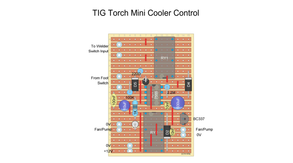
The whole circuit can be built on a piece of stripboard:
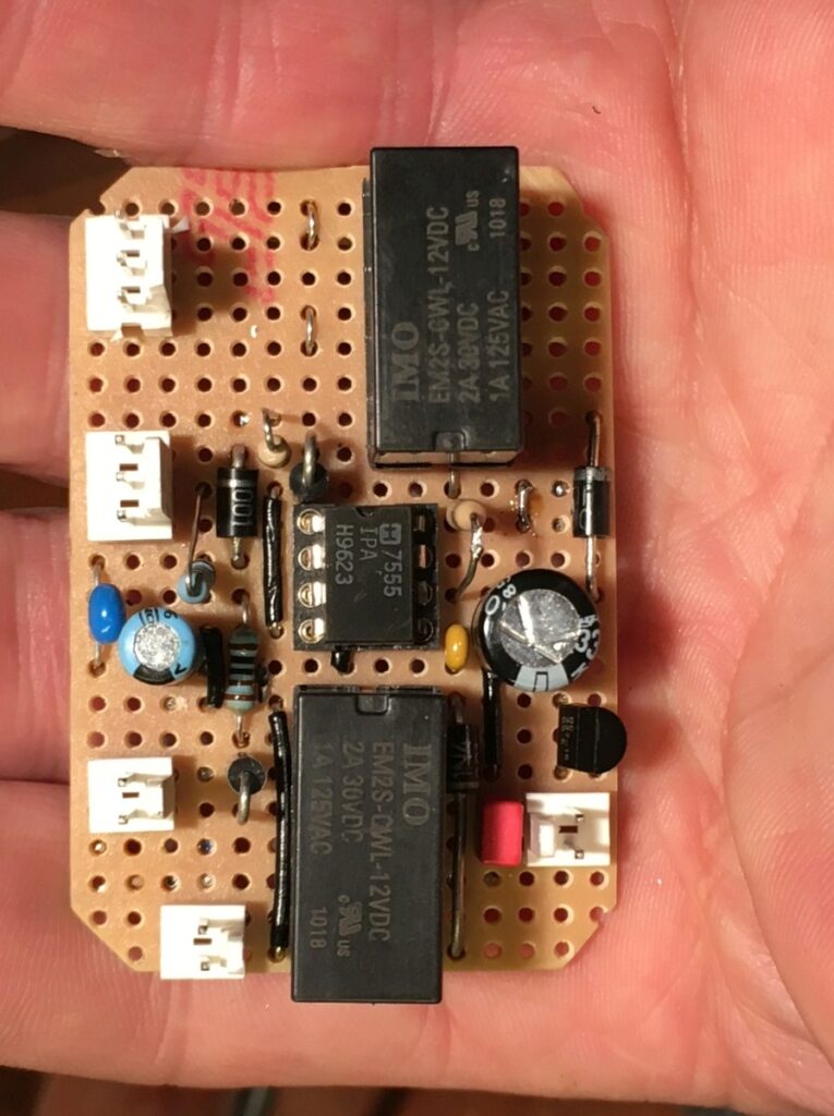
The electronics live in the small black box in the base of the unit
I added a perforated metal cover (the holes in the top are blocked by a sheet of plastic to stop rubbish falling into the works, but the holes in the sides are open to allow airflow).
I wasn’t sure how quickly it might heat up, so also added an LCD thermometer to the tank:
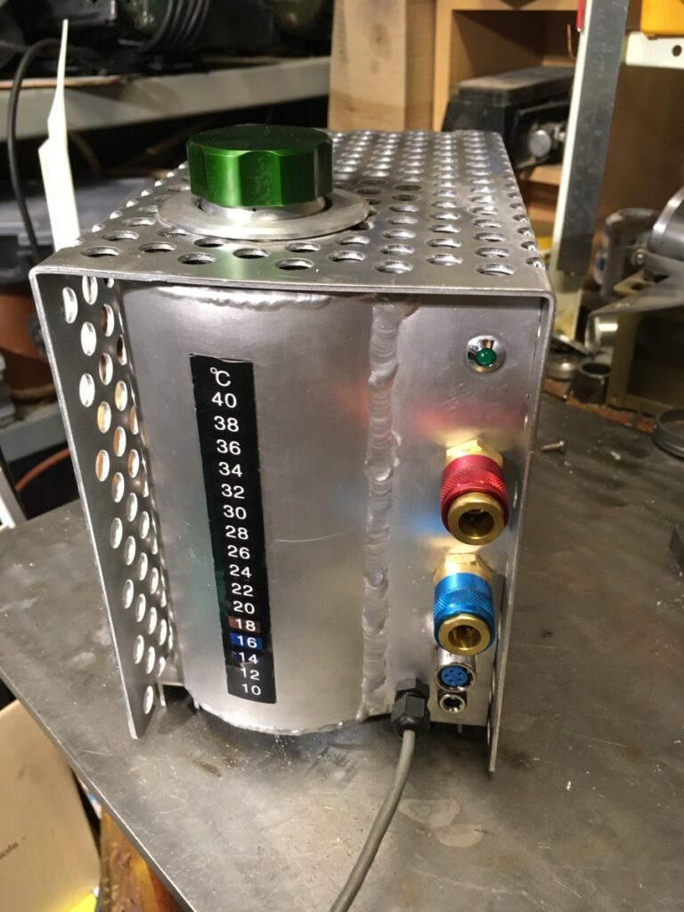
From top to bottom :
- LED to show when the pump is running
- Cooling water return (red)
- Cooling water flow (blue)
- Torch / pedal socket
- Flying lead to welder socket
- 12V DC from a plug-in adapter
Here it is connected to my welder. I am using aluminium / brass safe antifreeze as a coolant.
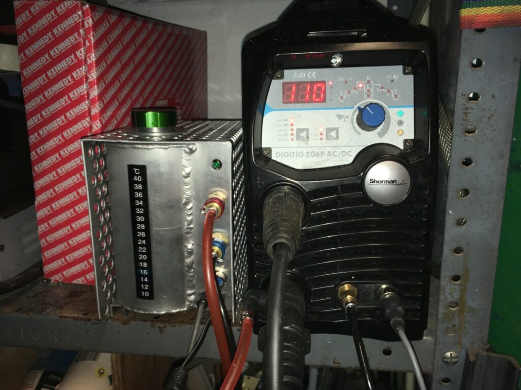
I’ve done quite a bit of welding with it since, and I must say, it seems to work very well for the way I weld. The coolant temperature doesn’t really increase much (a few degrees after an intensive session).
I doubt that it would survive in a commercial setting, but as a hobby unit, I’m really pleased with it.