
Our van (in common with other ‘Sevel’ vans – the Ducato and Boxer) draws a small amount of power from the vehicle battery, even when switched off and locked up. Some models come with an isolation button on the ignition switch, but ours doesn’t. If the van isn’t driven regularly, the vehicle battery suffers because of this – sometimes to the point where there isn’t enough power to start the van. (Trying to start the van with a weak or flat battery has been known to cause problems with the vehicle and airbag ECU especially).
There are several devices available that will trickle charge the vehicle battery from the leisure batteries if the van isn’t going to be used for a while (assuming that the leisure batteries are kept topped up by solar or a mains charger).
For example, I am aware of:
- CSB2 from Leisure Lines
- Votronic Battery Master
- Vanbitz Battery Master (different to the Votronic one)
But I fancied building my own…
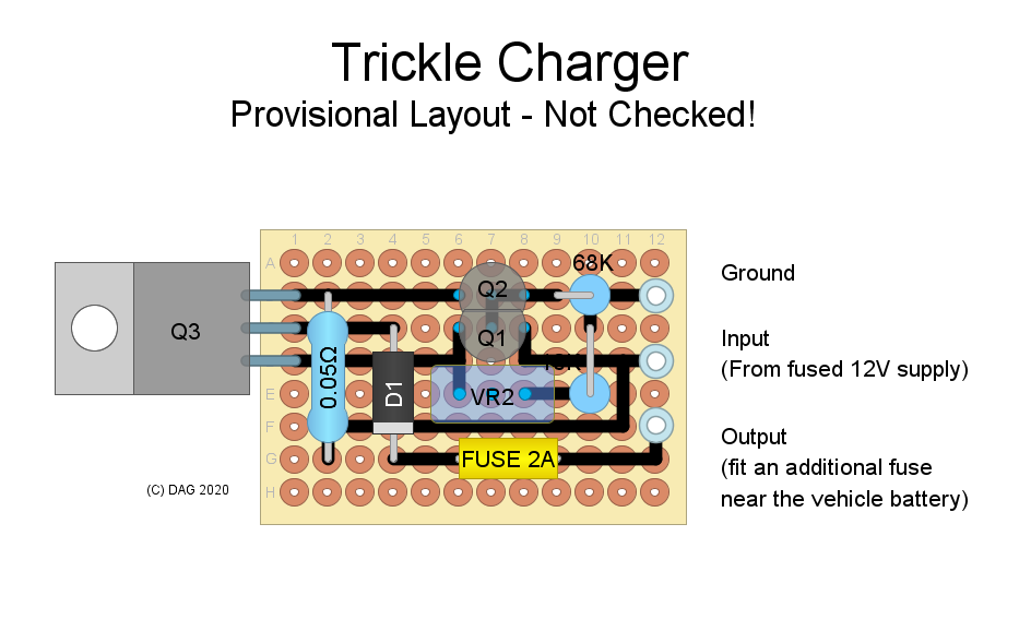
This simple circuit which gives a constant 0.5 amp current for trickle charging the starter battery. It is protected against reverse current flow from the starter battery.
The current should remain roughly constant until the starter battery is roughly 0.5V less than the leisure battery.
It’s important to fit the fuse on the output (F3 in the schematic) close to the relevant battery. F2 is a thermal fuse included to protect the unit in the event of overheating or faults – the supply into it must be fused to suit the wiring elsewhere.
Q1 and Q2 should really be a matched pair, but this isn’t a critical application, and a couple of transistors from the same batch would probably be OK (I bought a bag of 10 and matched up a pair with the same Hfe). They need to be in close thermal contact (I put them ‘face to face’ with a little heatsink compound in between and heatshrinked them together).
Check the current you get after building – this will depend on how closely matched Q1 & Q2 are. You can replace R1 with a 10K resistor in series with a 50k pot for an adjustable output.
I built it on a small piece of perf-board and fixed Q1 to the case to act as a heatsink (it shouldn’t get warm, other than under fault conditions).
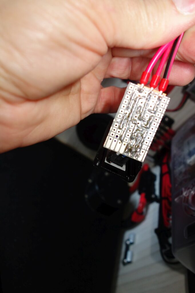
The 12V supply could come from a fused connection from the camper electrics, but I decided to feed it from the ‘LOAD’ output of a solar charge controller instead. Using the LOAD output has the advantage that it can be set to switch on when there is sufficient power available, and to switch off to protect the leisure batteries when there isn’t.
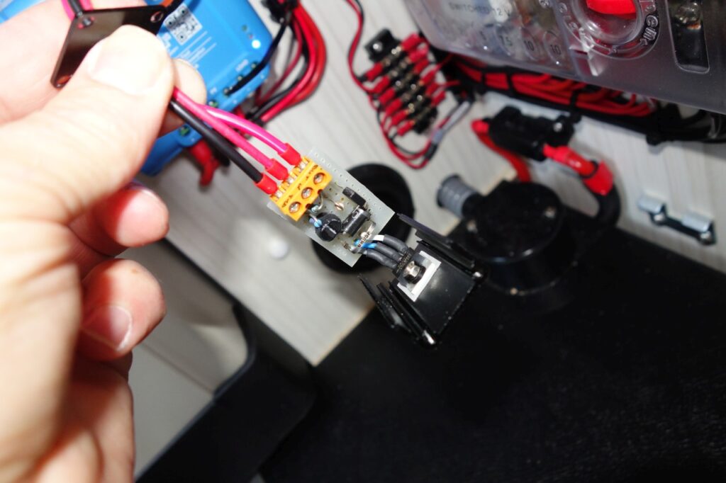
This is the unit wired into the van electrics:
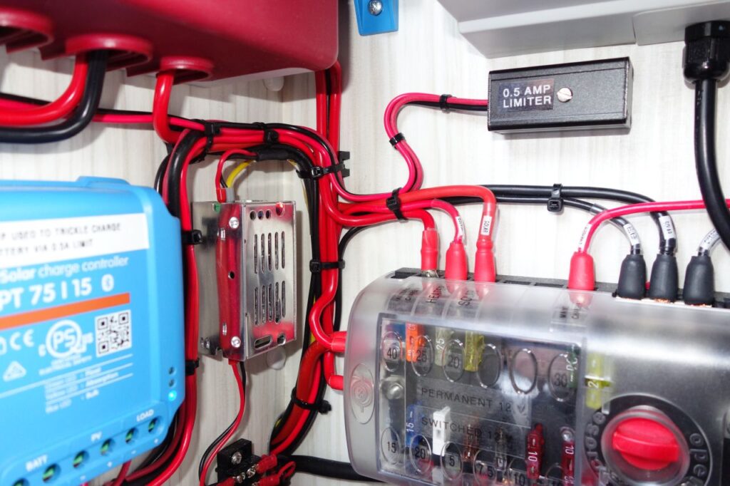
The output is connected through to the cab battery via an in-line fuse holder near the battery terminal.
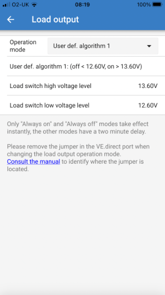
The default configuration of the solar controller is for the load output to be on when there is no input from the panels (‘Street Lighting’ mode). This needs to be reconfigured to be on when there is solar available and off otherwise.
This is easy to do on the Victron MPPT 75/15 using a ‘user algorithm’ as shown below:
I hope this is of interest, but please note: