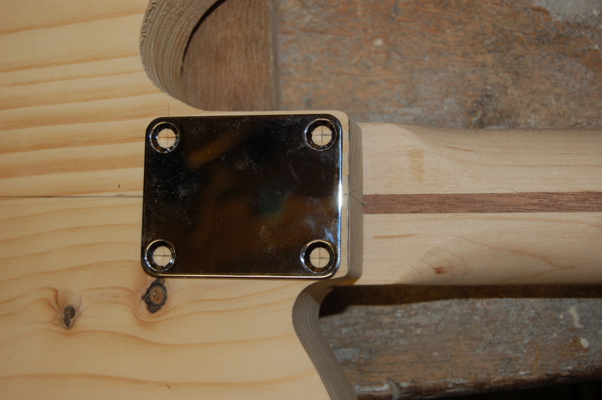
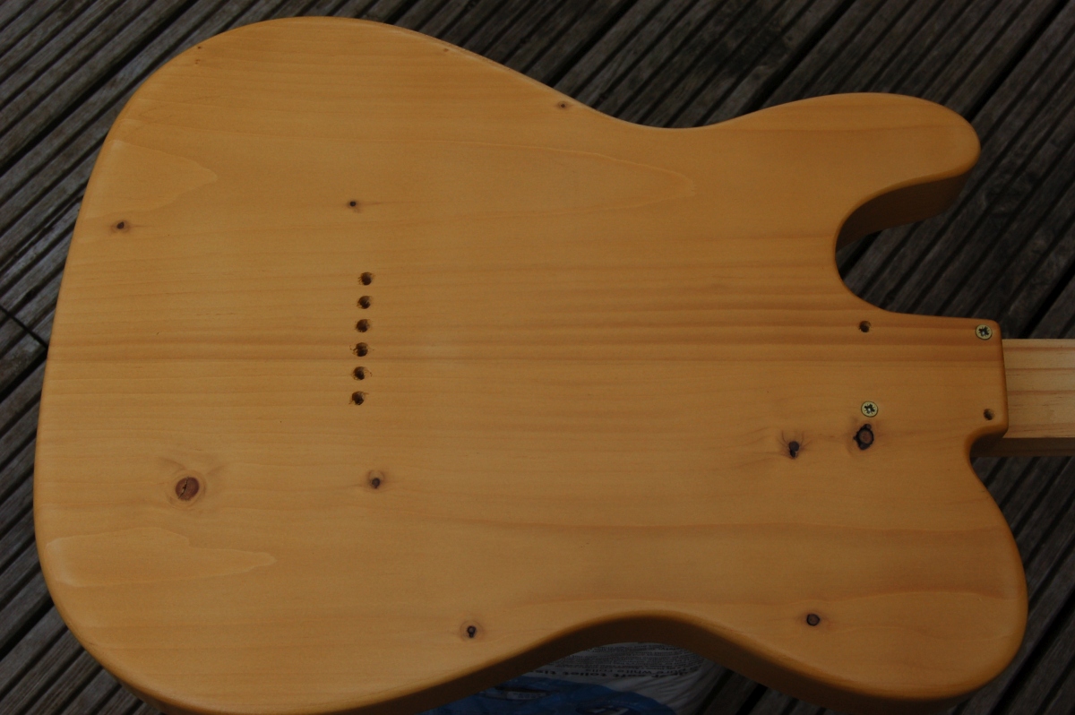
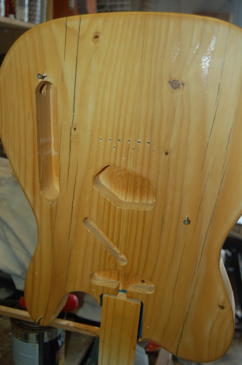
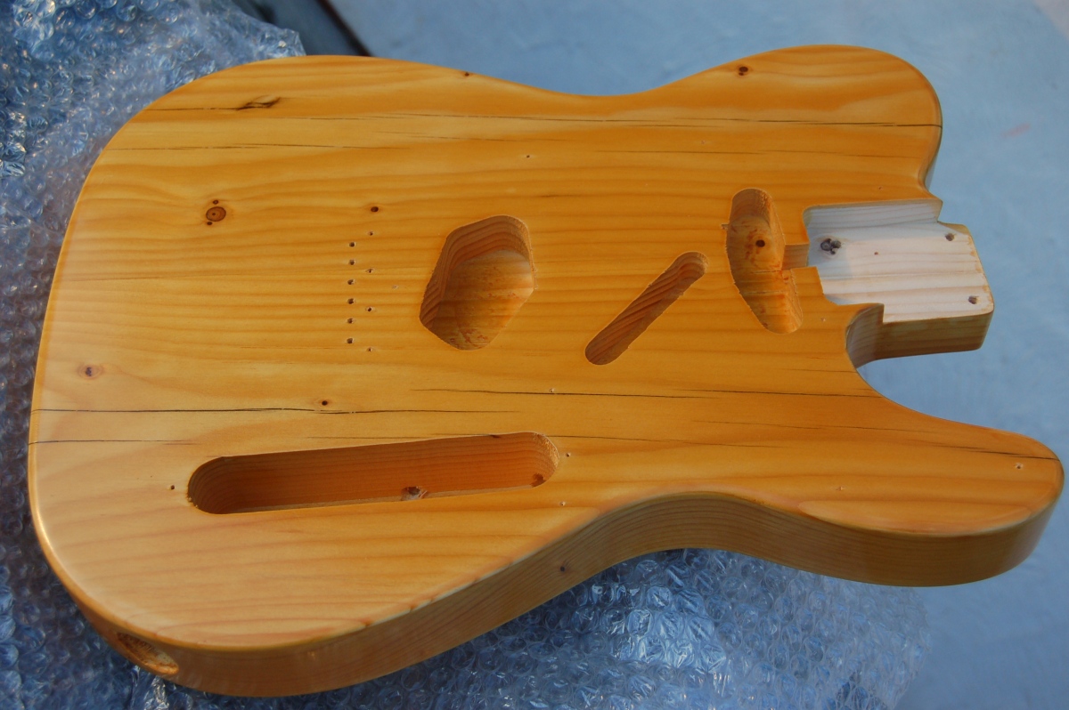
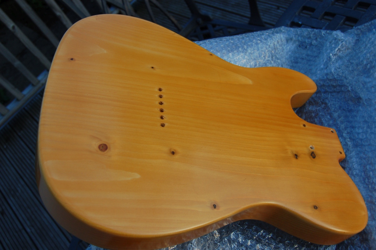
Neck screw holes
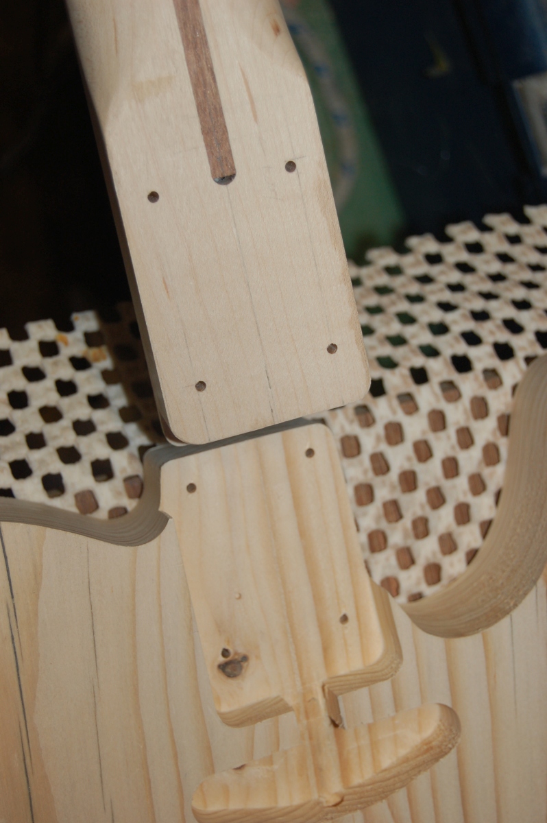
I marked the position of the neck screw holes out on the back of the body – Looks like I had got a bit enthusiastic with the sanding as the neck plate comes quite close to the edge of the body.
I drilled 3mm holes through the body only in the drill press to get them straight, but before I drilled the holes into the neck, I wanted to get the neck properly lined up with the bridge.
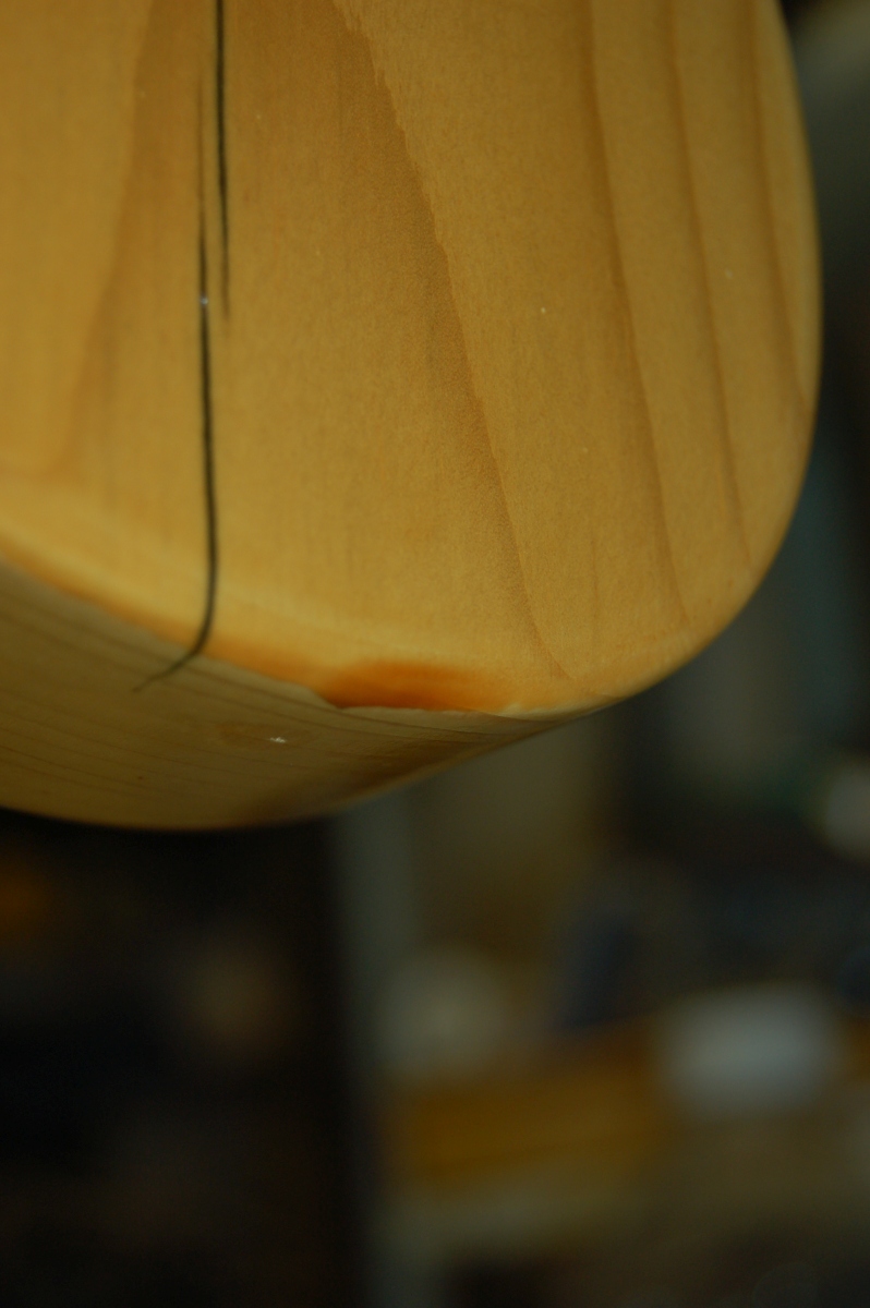
With the neck clamped into position, I ran some fishing line from the outer saddles of the bridge up through the headstock and positioned it roughly where the 1st and 6th strings would be at the nut:
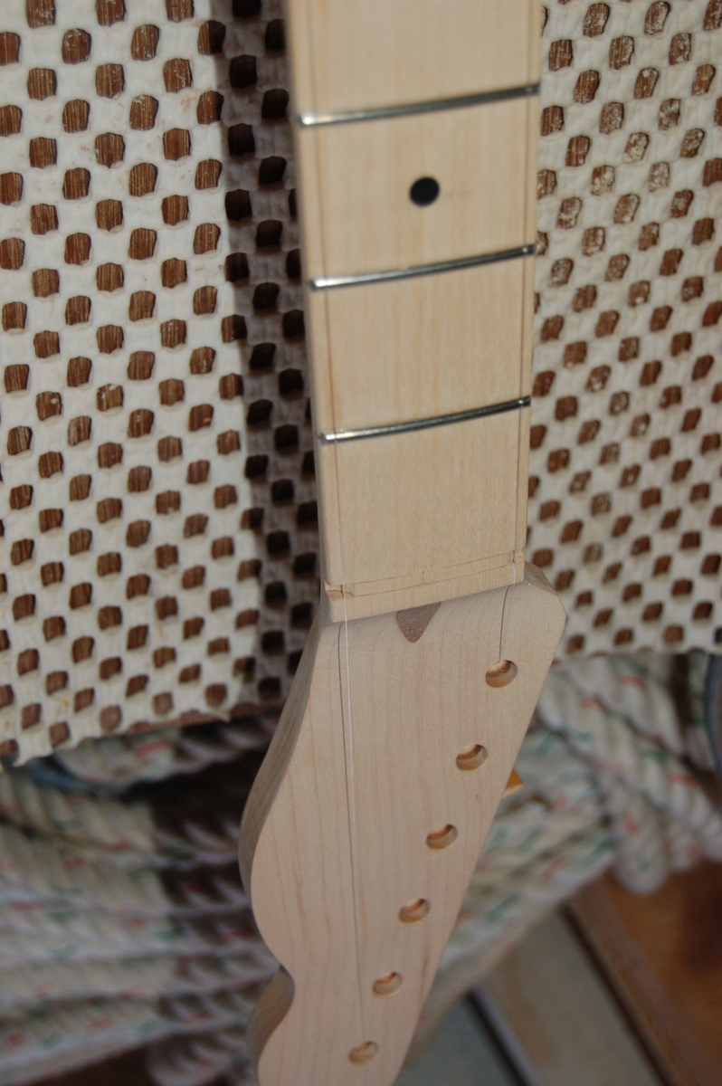
I’d marked the centre of the bridge (on masking tape) so I could hold the bridge on the centre line of the body to check where the strings would run. It only needed a very slight nudge on the neck to get the string spacing even at the neck heel before tightening the clamp up to hold the neck in position while I drilled the screw holes.
Check neck screw against 3mm drill bit to set depth:
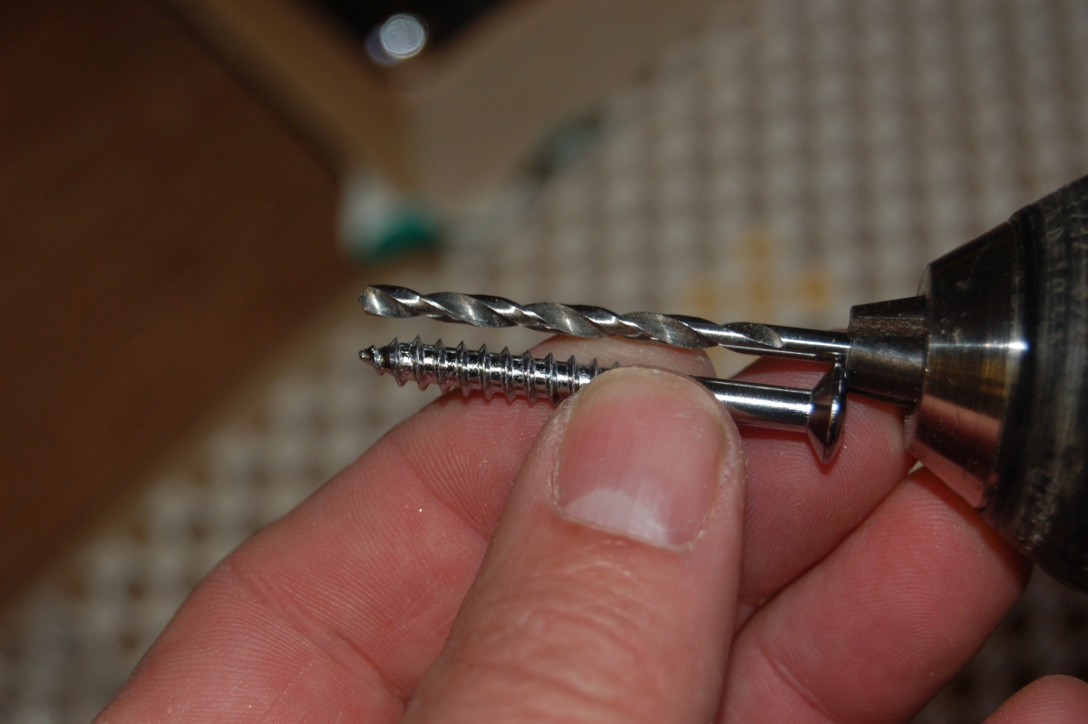
Double check that this won’t go straight through the neck!
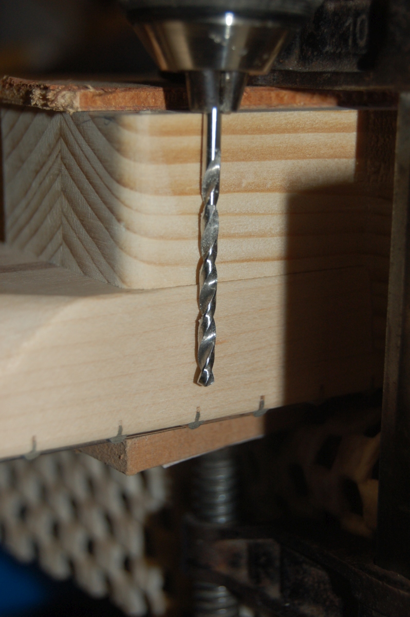
Then just drill down using the existing 3mm holes in the body as a guide:
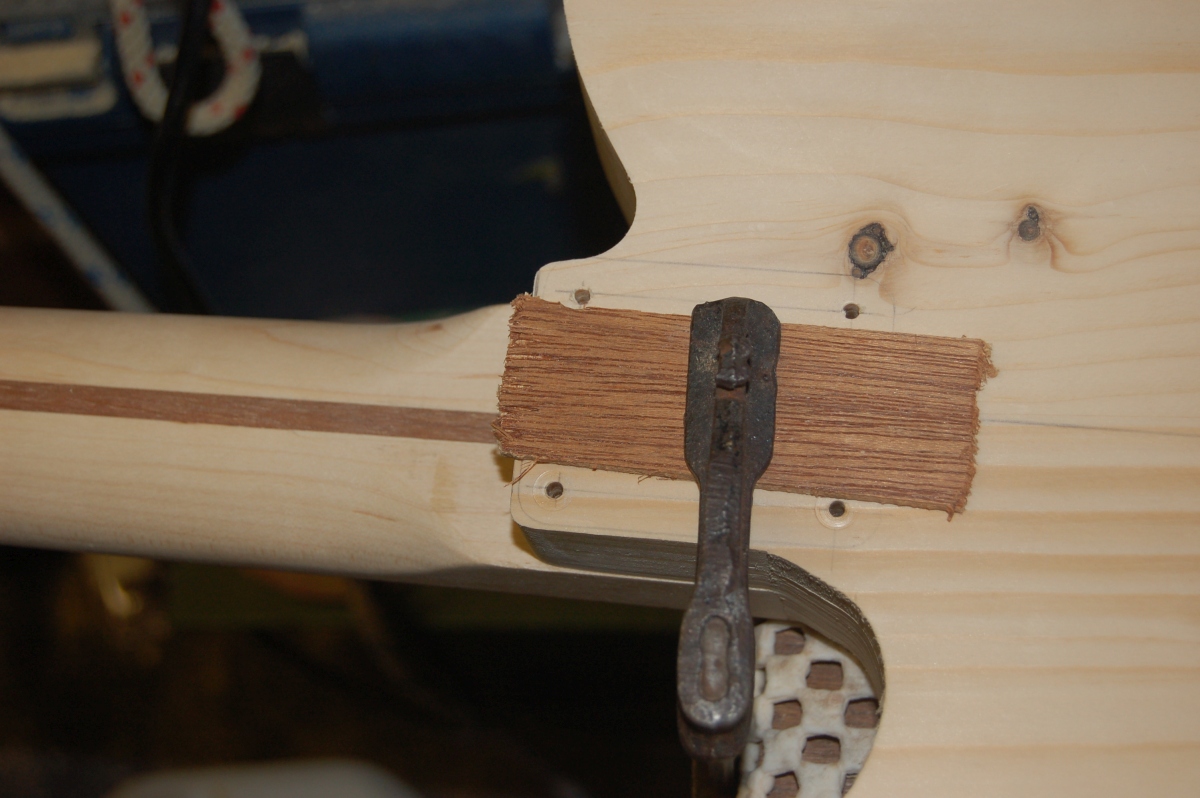
Finally, enlarge the holes in the body to be clear the thread of the neck screws (5mm IIRC):
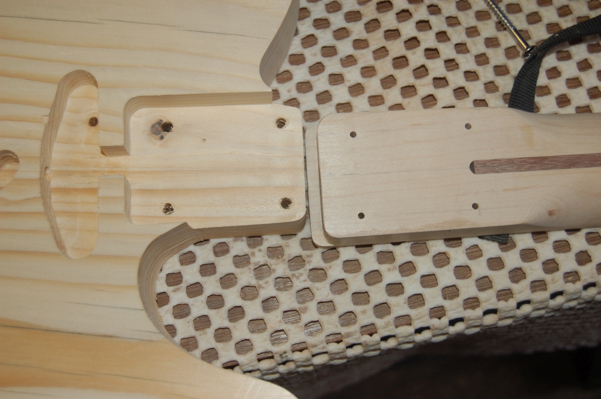
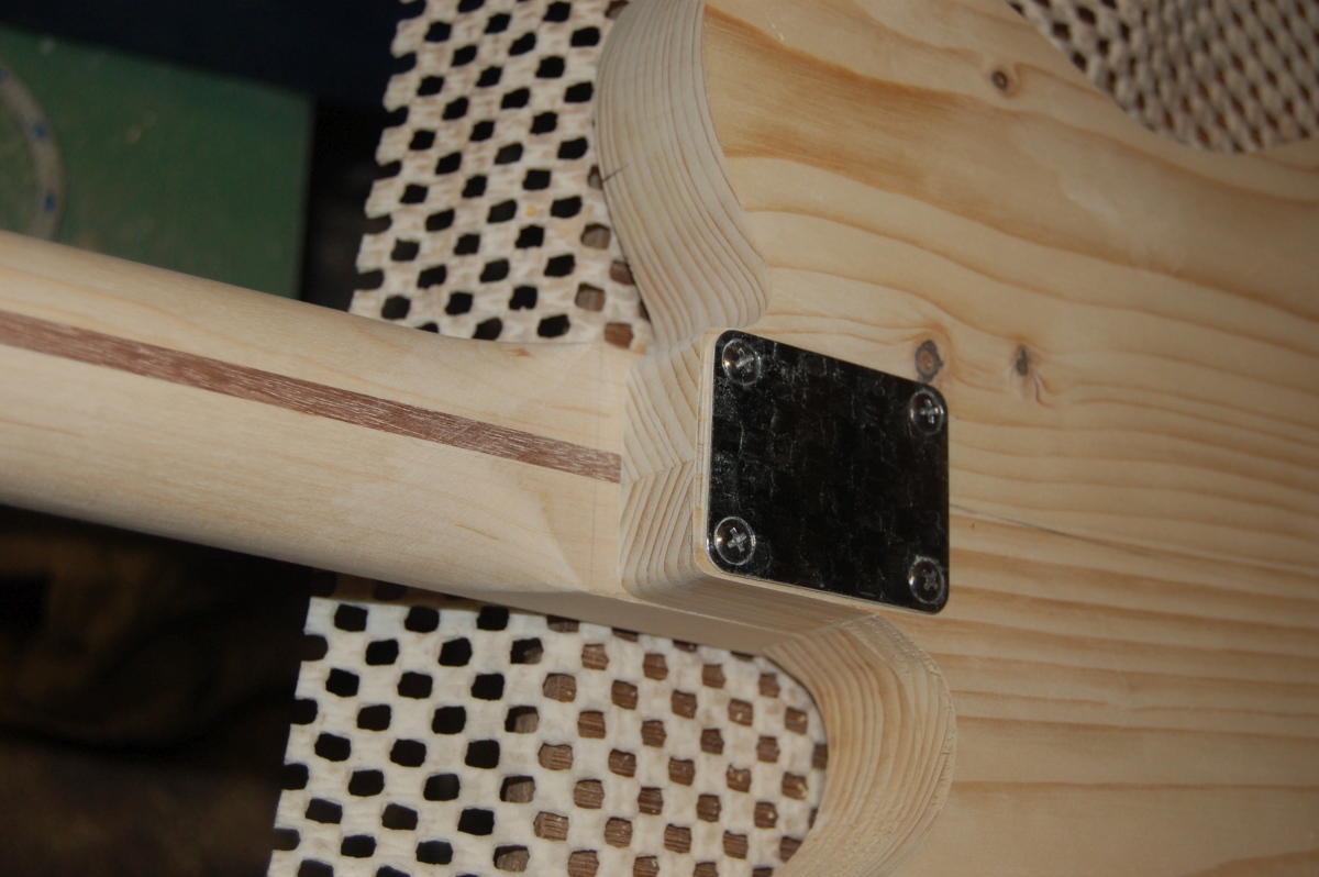
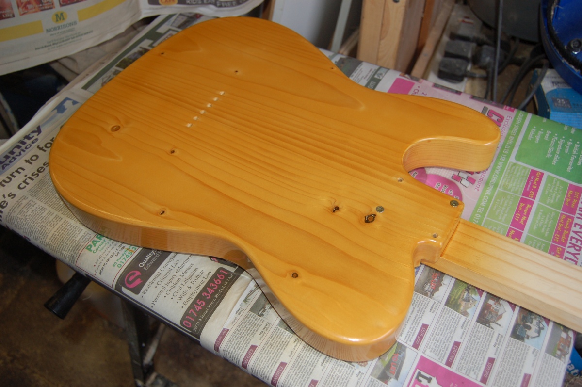
Then screw it all together for a test fit:
Bridge
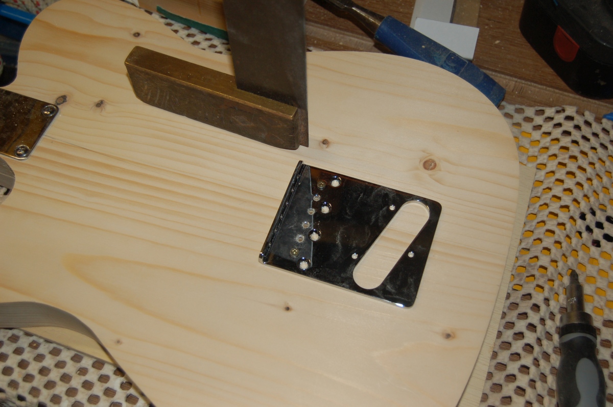
With the neck fitted, I could measure for the correct bridge placement – The Gotoh bridge I had picked up on ebay only has a small range of intonation adjustment (for a tele). I moved the intonation adjustment all the way forwards, and moved the bridge along the centre line until it measured 25.5″ from the saddle to the fretboard side of the nut and marked the bridge position. I carefully drilled for and fitted a couple of the bridge mounting screws and checked that everything still matched up. Then I had a cup of tea, and came back and checked again.
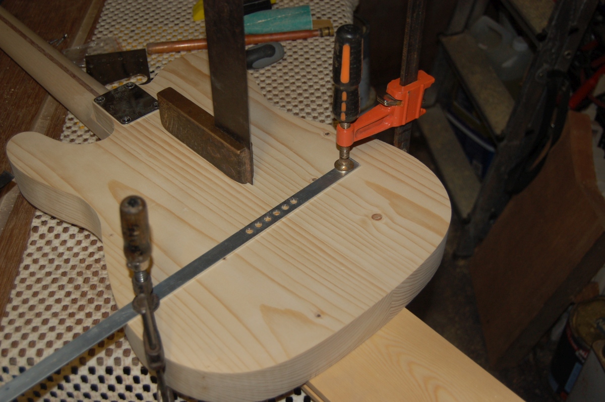
It all semed to be OK, so I drilled the other two mounting holes and made a start on the string holes through the body. Aside from the neck, this was the aspect that I was most bothered about being able to do. The holes are too far into the body to be able to drill them in my (cheap B&Q) pillar drill, so they would have to be done by hand.
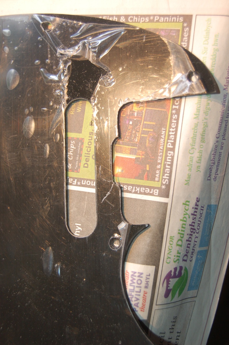
I’m crap at cutting or drilling anything in a straight line, so I had set squares balanced on the body to sight the drill against to try and help me drill straight. The best help, though came from the chrome plated bridge. I was using the bridge as a template to position the holes, and from a dim memory somewhere remembered a tip about keeping the reflection of the drill bit in a straight line to drill square to the surface:
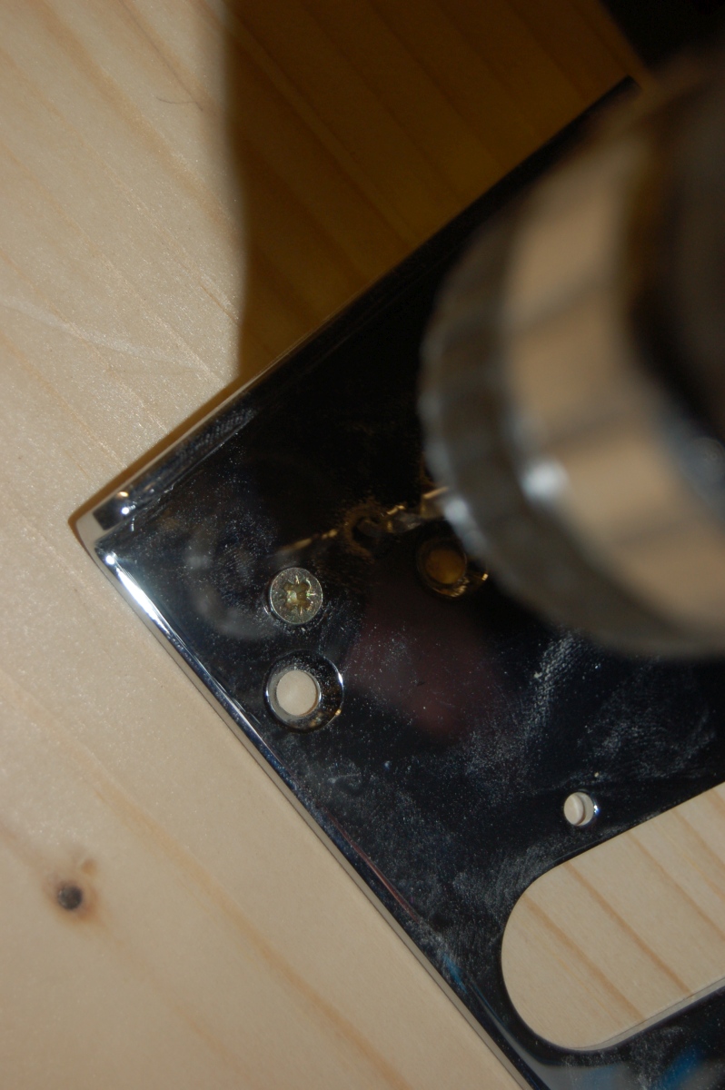
If there’s a kink between the drill bit and its reflection, then you’re drilling off line.
Anyway, I drilled the two outer holes right through to the back of the body, but only drilled the other 4 holes about half way through then removed the bridge.
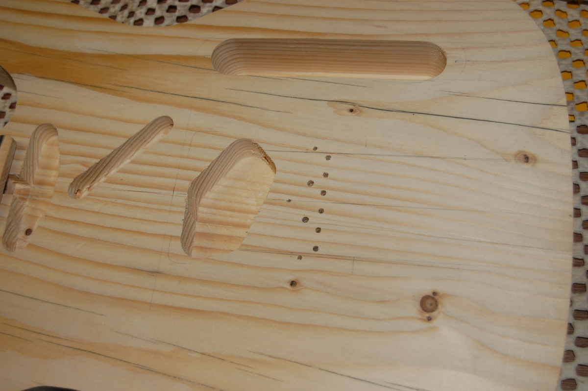
I flipped the body over and used a couple of loose fitting screws to line the outer string holes of the bridge up with the holes through the body. The holes spacing was ~1 mm off on the back of the body, but close enough.
Using the same technique as before, I drilled through to meet the middle 4 holes using the bridge as a template.
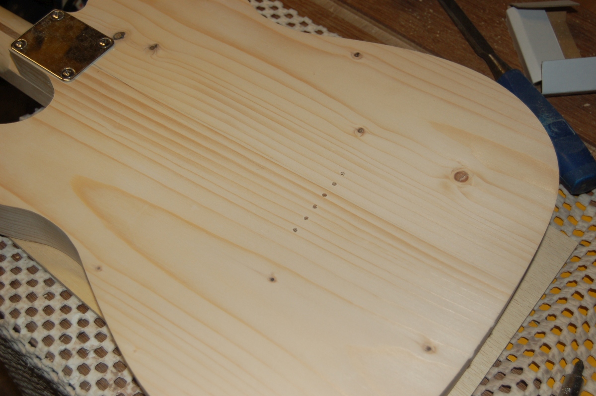
Everything met up – I’ll settle for that!
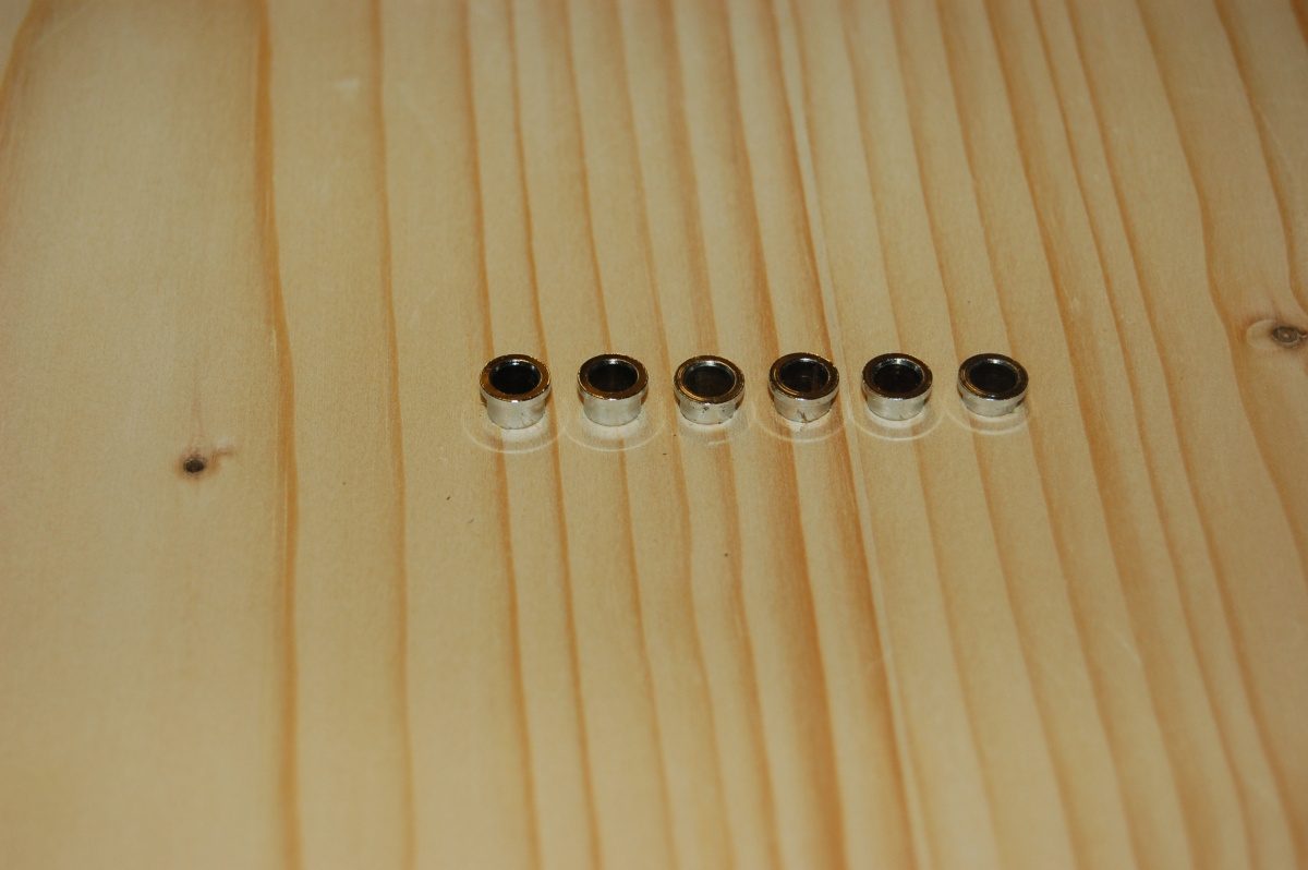
I drilled some similar holes on some scrap and tried enlarging them for ferrules:
Ok, they’re different heights (which makes it look worse), but they’re not in line either:
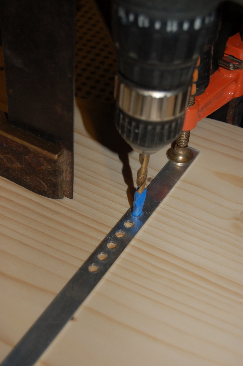
So I decided some assistance was needed. I used the bridge as a template again to drill some 3mm holes in a strip of aluminium, and then put this against a fence on the drill press to enlarge them:
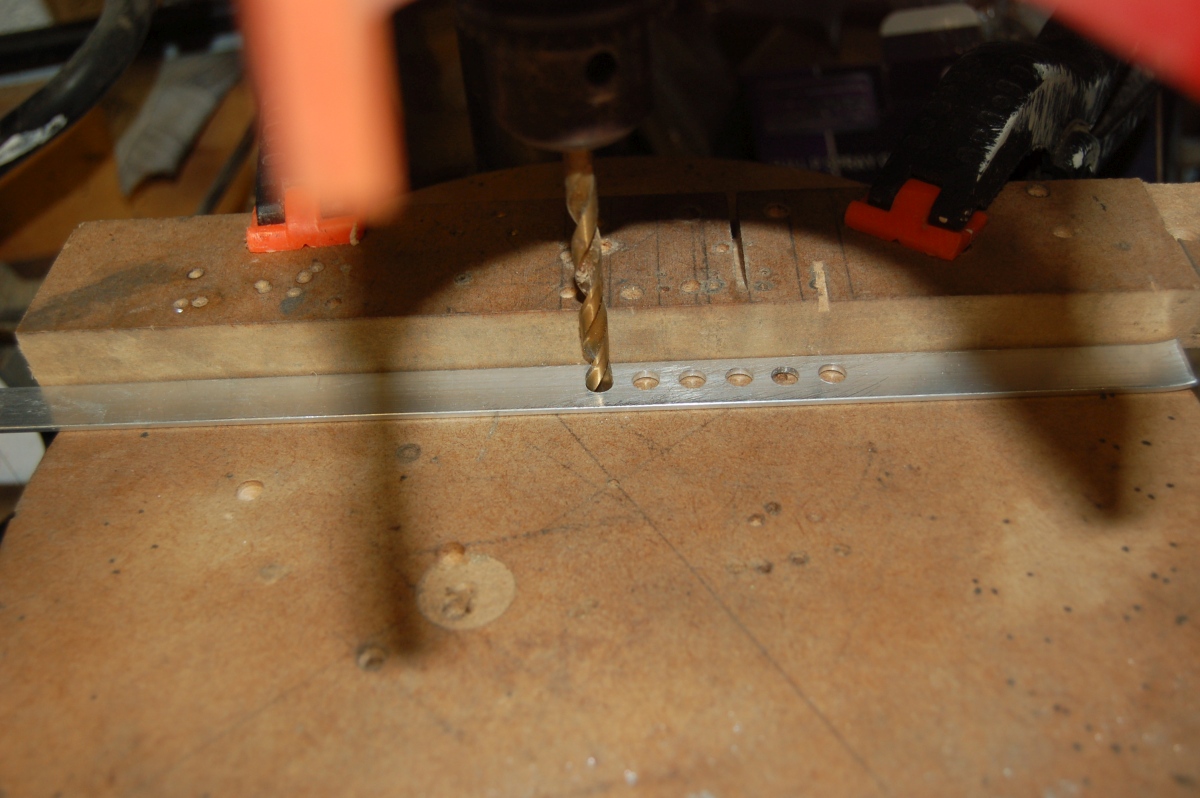
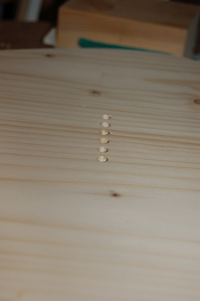
I could then clamp this strip over the string holes in the back of the body and use it as a guide to drill through for the ferrules:
This worked a treat:
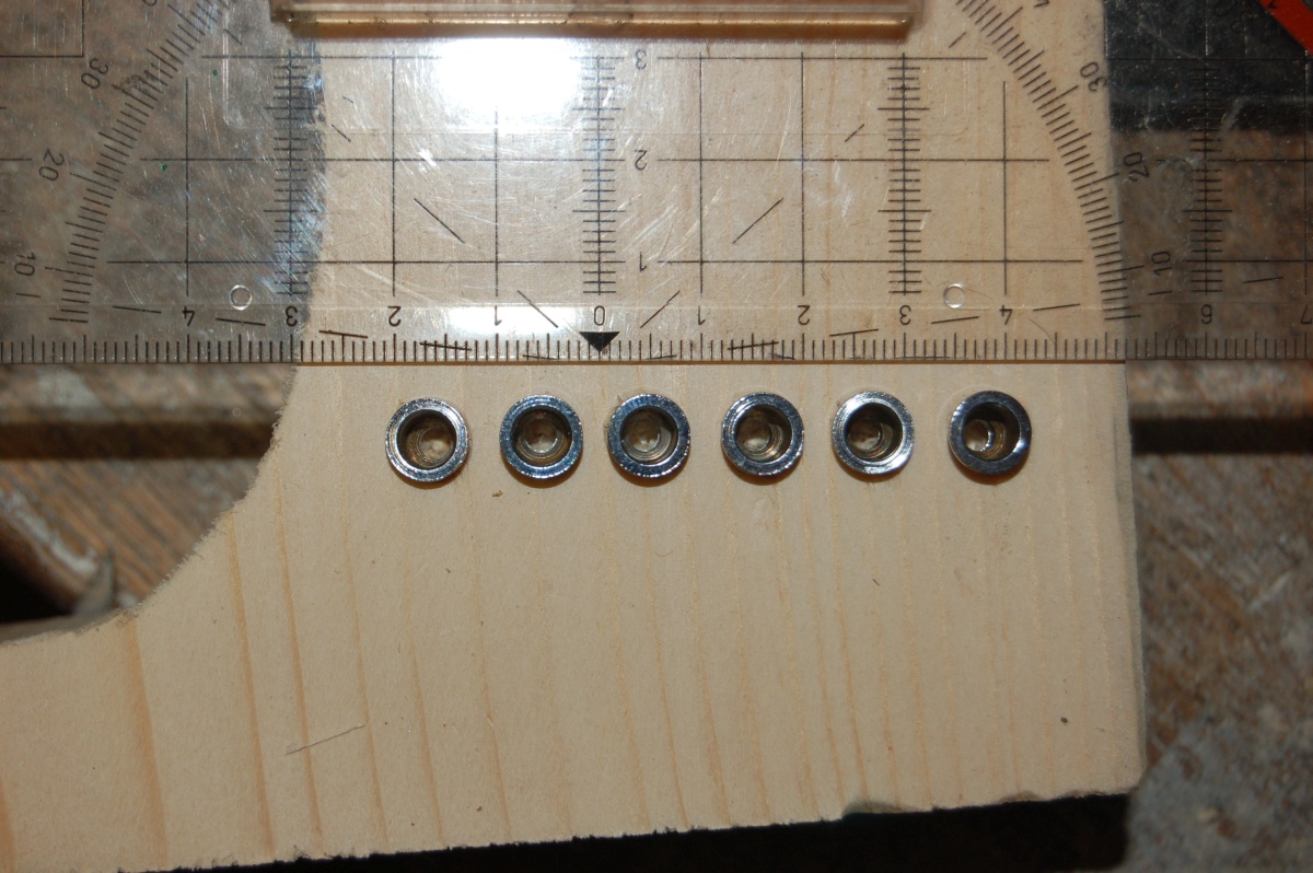
With the ferrules pushed in as far as I dared (the body needs to be finished before I fit them for real):
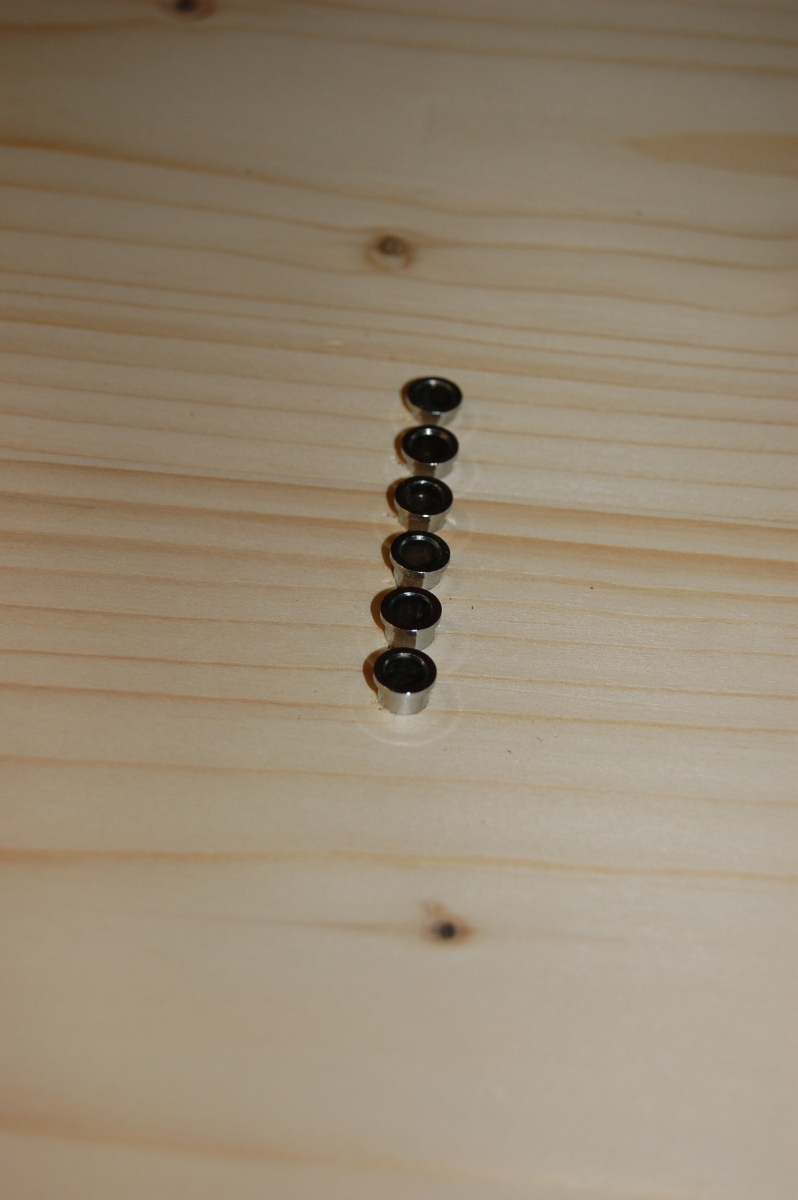
WELL chuffed with that.
I was very pleased with the way the ferrules came out – better than I could have hoped for really, and the template pulled the spacing of the outer holes back into line.
Final jobs on the body
Just a few jobs left to do on the body:
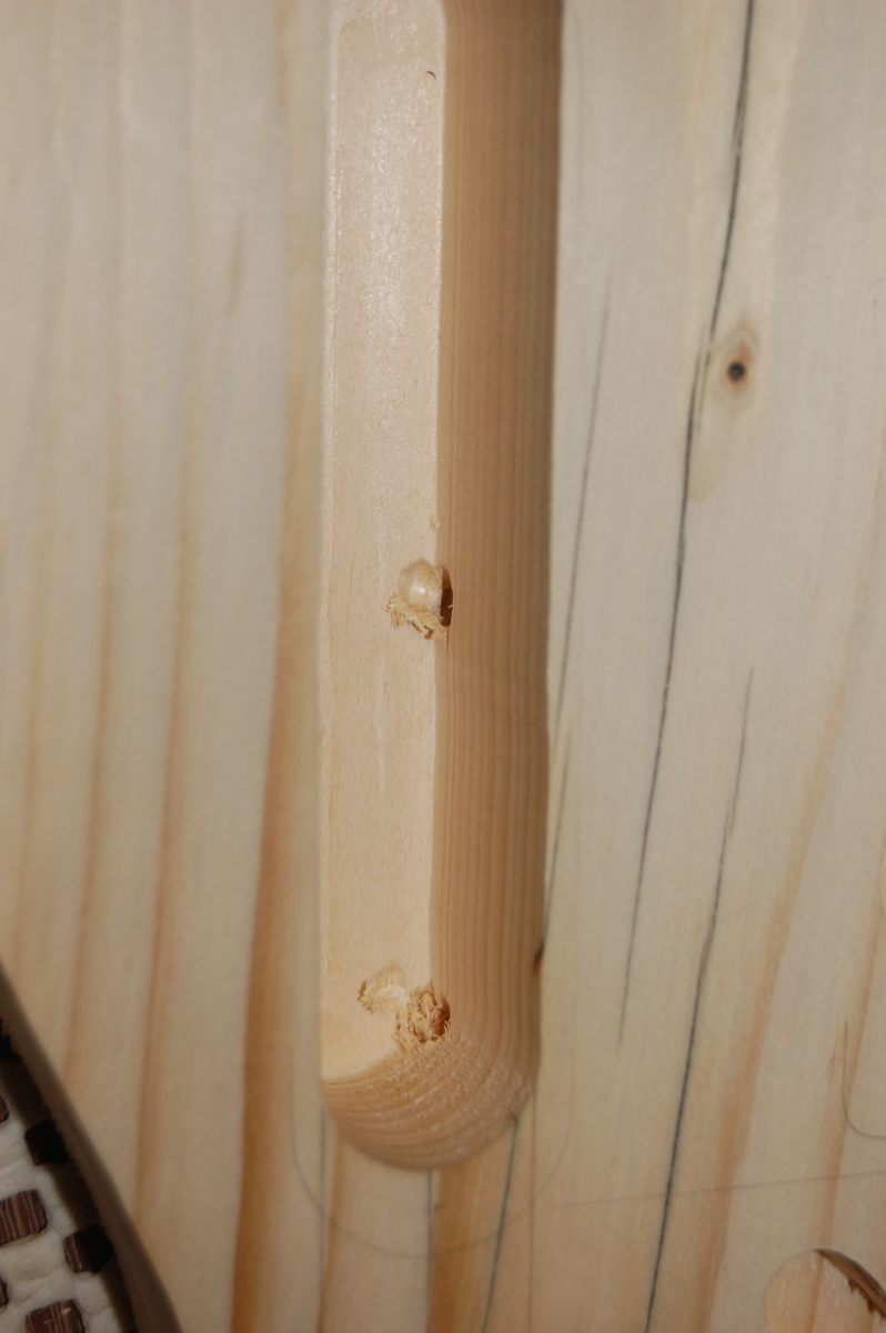
Drilling the holes between the cavities was straightforward enough
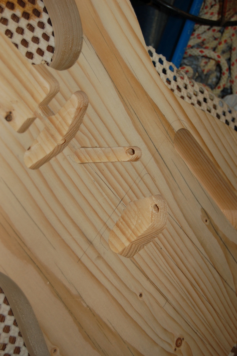
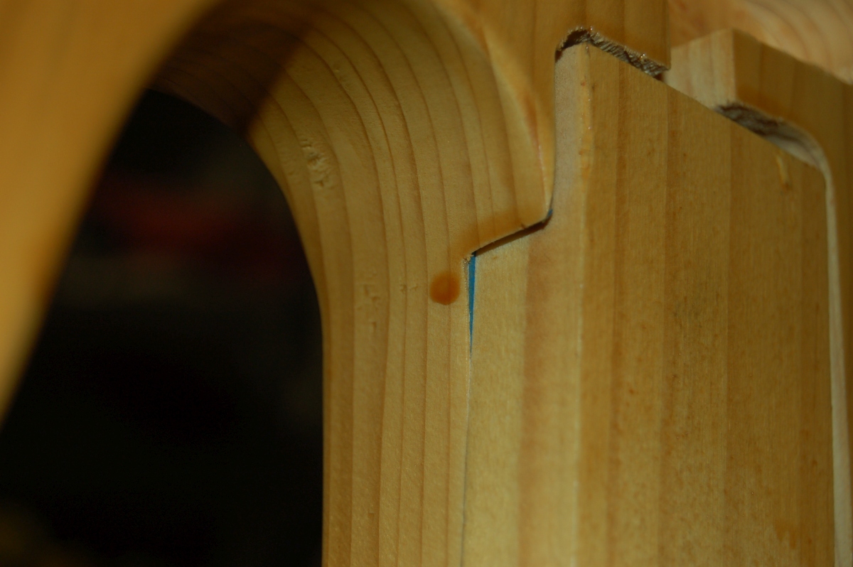
They came out closer to the bottom of the control cavity than I expected, though:
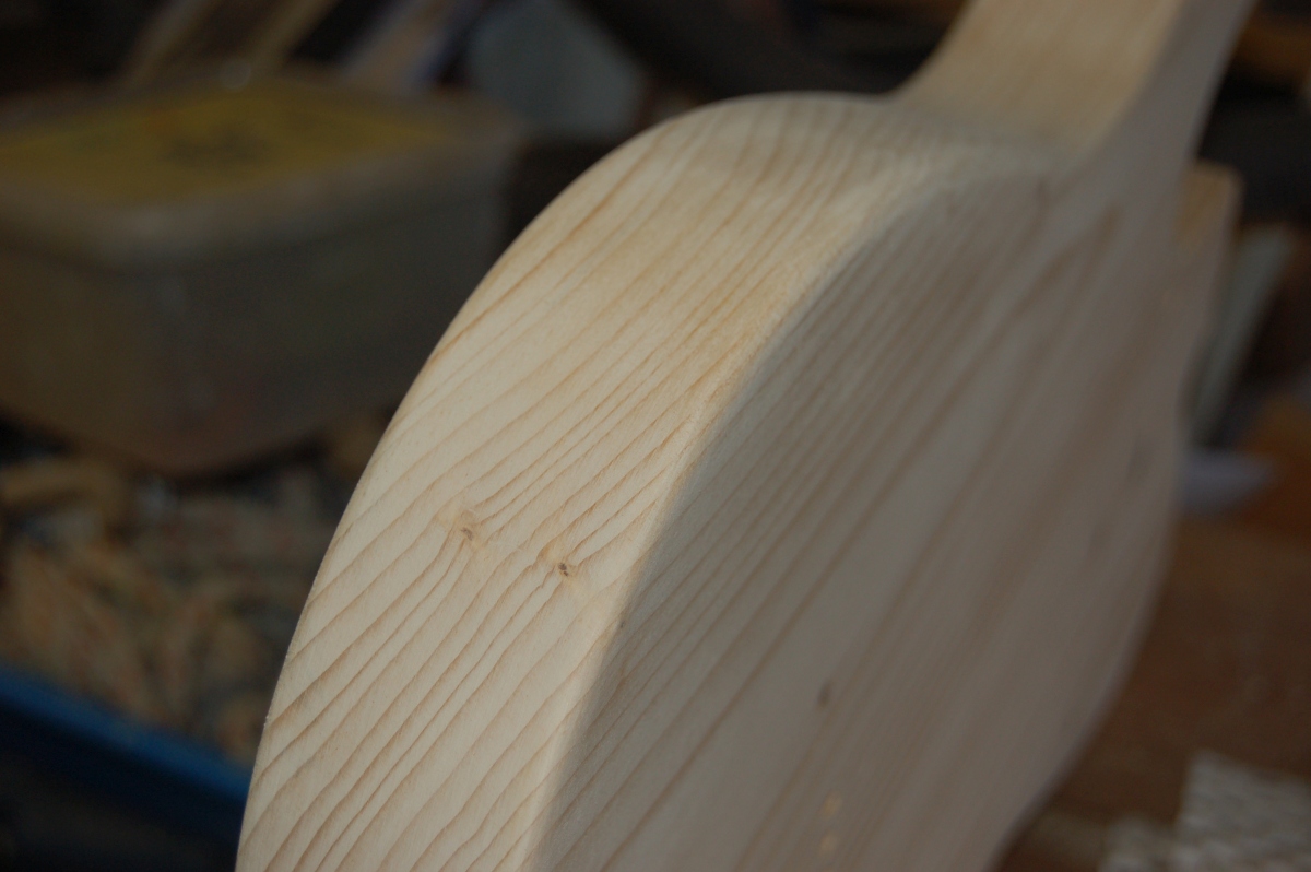
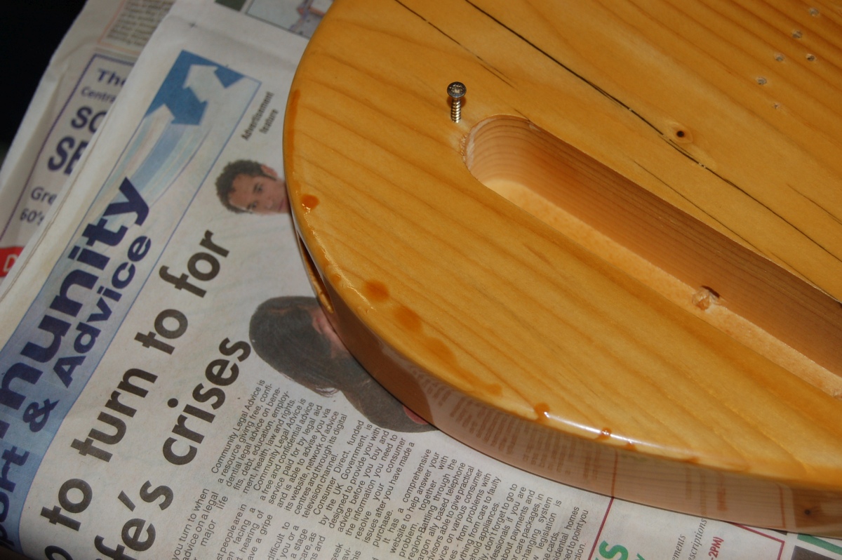
I was reluctantly resigned to sanding a radius on the edge of the body, but happened to get lucky on ebay. I’ve been looking for a cheap, small radius, roundover bit for ages – the cheap ones are all ~10mm radius, and the 3 – 4 mm radius ones are few and far between, and always seem to be ~£40+ professional ones.
Then I found a set of 6 different round-over bits between 3 and 10mm radius for £15. They were described as 1/4″ shank when I bought them, but they turned out to be 8mm shank when they arrived. Luckily I have an 8mm collet (the first time I’ve ever used it). They seem pretty decent (for cheap cutters), and the 4mm radius bit took the corners off the body in no time flat.
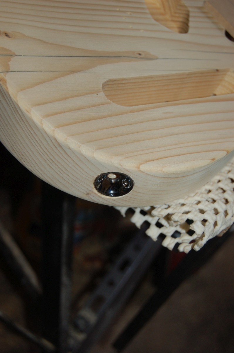
The last job before finish sanding was to drill for the jack socket. The electrosocket needed a 25mm diameter recess a few mm deep for the rim with a 22mm hole behind it for the body of the socket. The only 25mm drill bit I had was a nasty spade bit which aren’t renown for their neatness. I tried it out on some scrap and it seemed to drill a reasonably clean hole, so I went with it
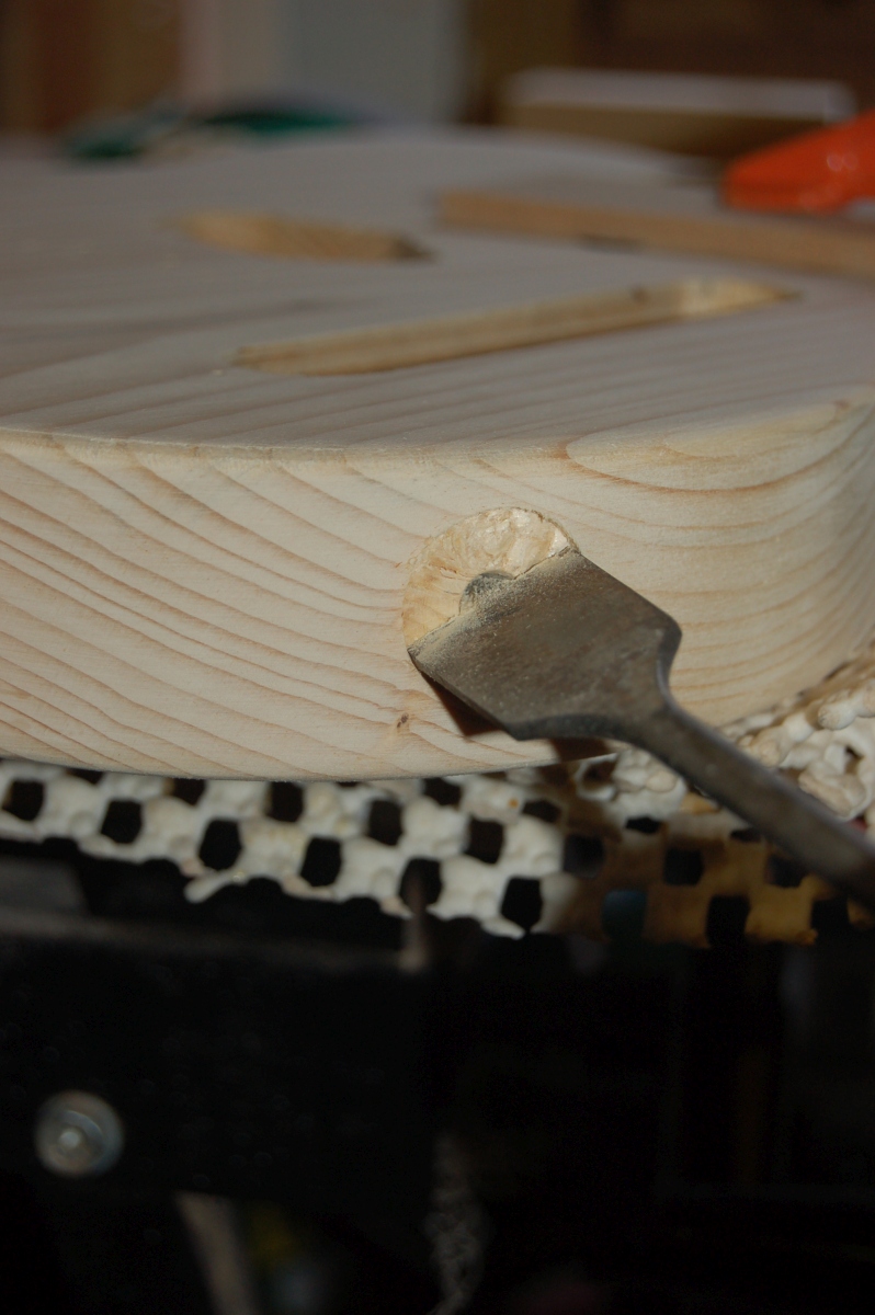
I wedged packing in the control cavity before the smaller hole broke through to try and keep things neat.
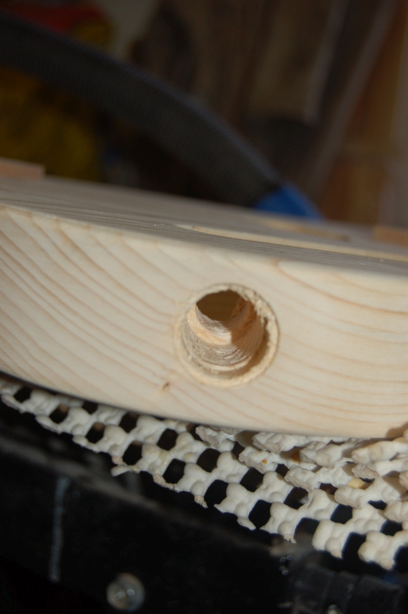
Not the best in the world, but it’ll do,
Then sanding, sanding, sanding,,,,,
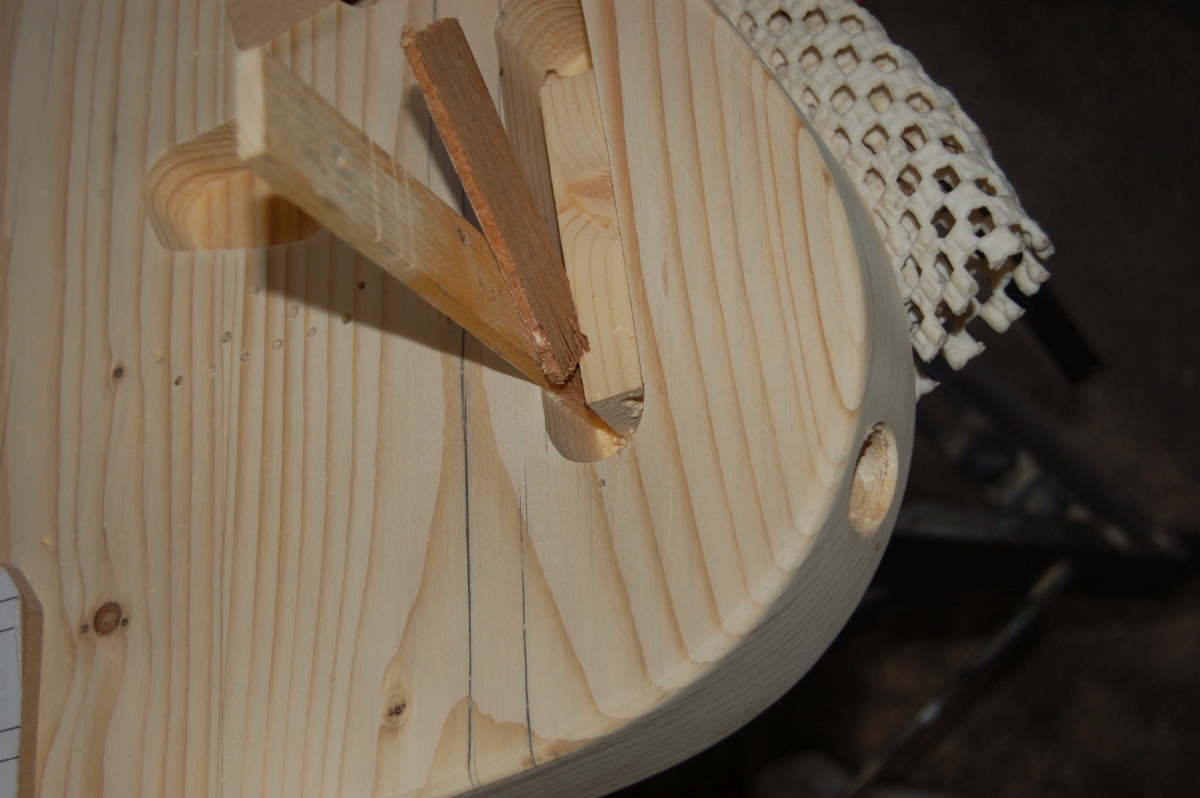
Early on, I managed to get the corner of a piece of sandpaper folded under and put a big gouge in the back before I realised:
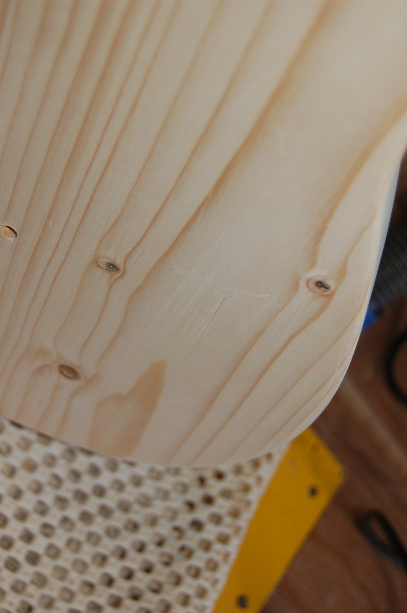
I brought the body into the house, and when nobody was looking, I covered it with a damp cloth and ran the steam iron over it. It brought the gouge out pretty much completely!
There were a couple of spots where the routing had torn out isolated fibres. This left pits that were too deep to remove by sanding. I tried to fill them with superglue which worked, but the glue soaked into the surrounding wood and left a stain that went in too far to sand out! :-/ Ho-hum, I’d intended that the body be somewhat ‘rustic’, so these stains will just add to that vibe (maybe).
Finishing
I wasn’t sure what sort of finish to use on the body: I wanted to see the weathering on the front, so it should be a transparent finish; I was desparate to avoid that sickly varnished pine look; ideally it would be something pretty hard as the raw wood was very soft, and cheap would be good, too.
I had 1/4 of a tin of this water based varnish left:
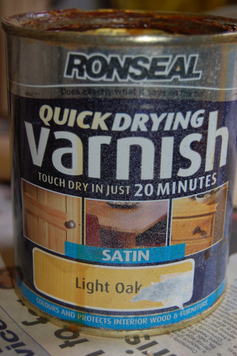
It had worn very well on the skirting boards in the house, but was an absolute pig to try and get smooth finish with a brush. I have a small spray gun…
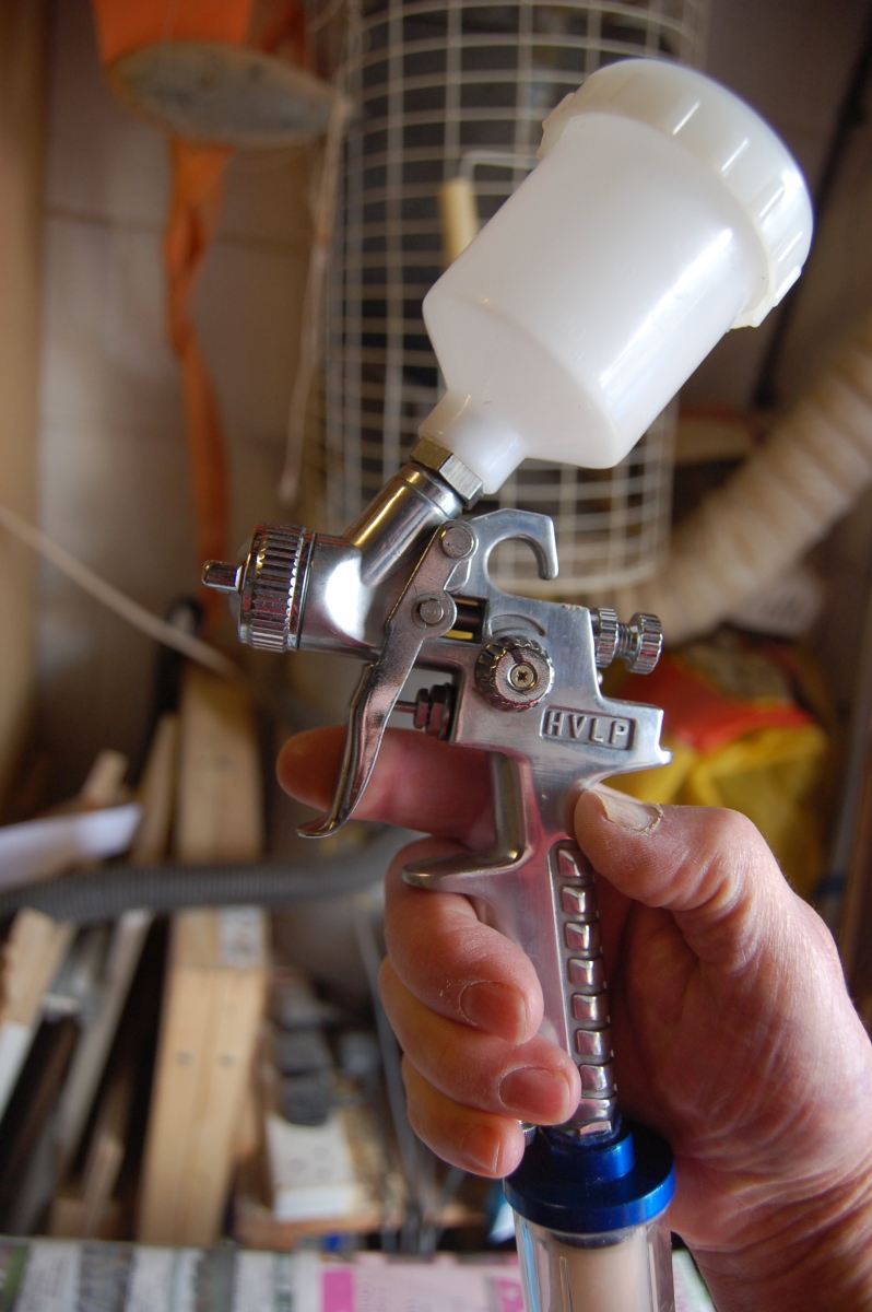
so I wondered if I could spray it…
I tried it without thinning to start with, and it seemed to work OK on some scrap, so I hit the body with a couple of coats and thought I was on to a winner:
The first coat went on quite ‘dry’, so I opened the paint needle up as far as possible for the second, but the surface was still very dry, and hadn’t really flowed out.
For the third coat, I tried thinning the remaining varnish with 5% water (it was quite alarming when adding the water, as the varnish went bright blue and milky until I stirred it up!). This went on quite nicely, and seemed to flow out well. When I came back to it, though, there were a number of runs which had appeared whilst drying:
Annoying, but I thought if I put a bit less paint on, and kept the body horizontal after spraying, that everything would be OK. So I carefully wet sanded the runs out (the varnish actually wet sands very well) and fitted some screws to the existing holes that I could use to support the body while it dried…
…and carefully went for the 4th coat.
Looking good…
Until I turned it over! 😡
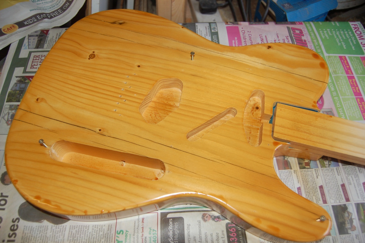
This was just silly! I’d been careful about how much I had been spraying, and it had looked perfect immediately after painting, and yet it was sitting in puddles !?
It occurred to me that what was probably happening was that the varnish wasn’t ‘going off’ quickly enough, so that it had time to run and pool. In hindsight, the problems probably coincided with the weather turning cold and damp.
So I wet sanded all the runs out again, put a fan heater in the shed for a few hours, warmed the last of the varnish and went for it again (5th coat!).
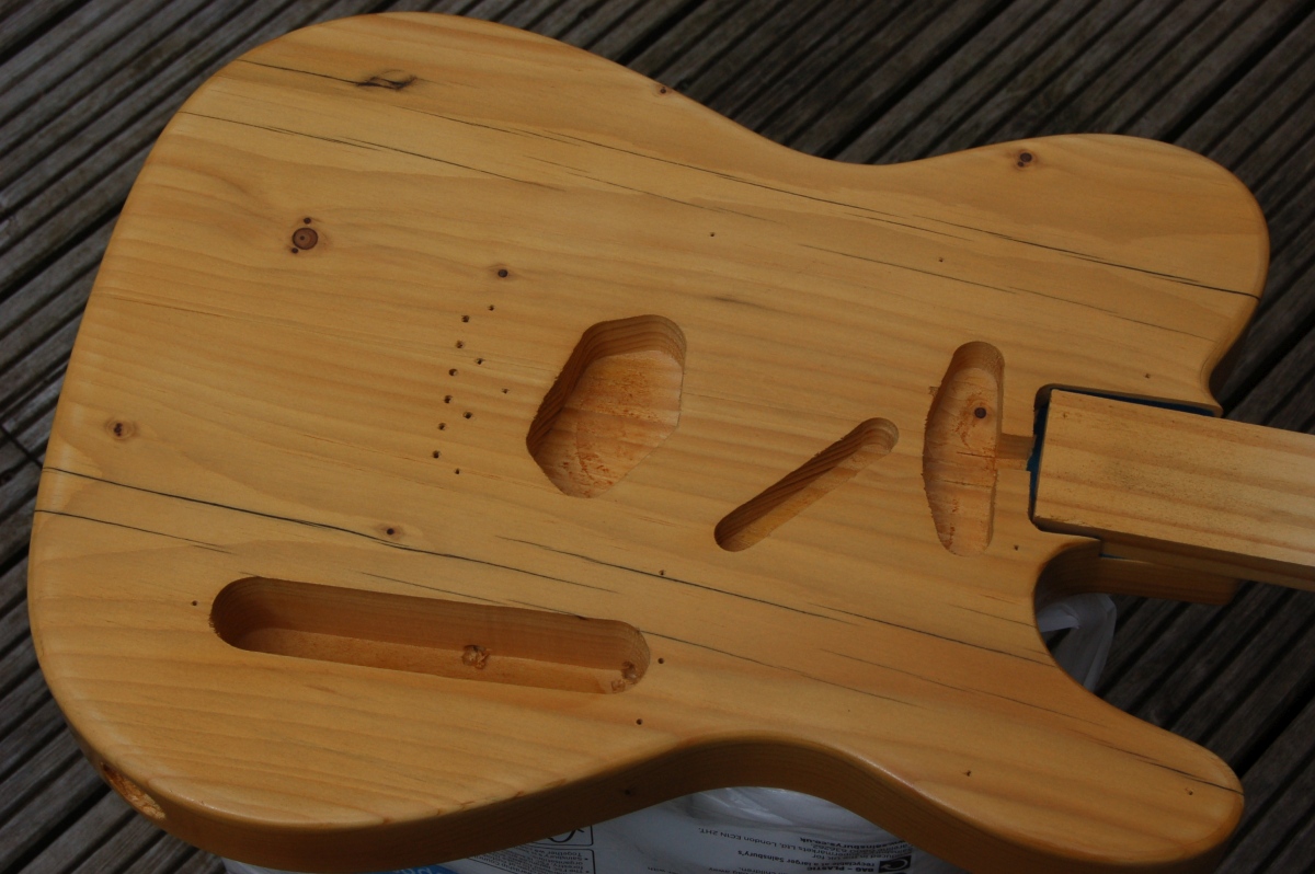
This time, it seemed to work OK:
In an ideal world, it could probably use another similar coat, but I’ve run out of varnish and enthusiasm for varnishing, so will stick with this. It’s supposed to look ‘rustic’ :^o
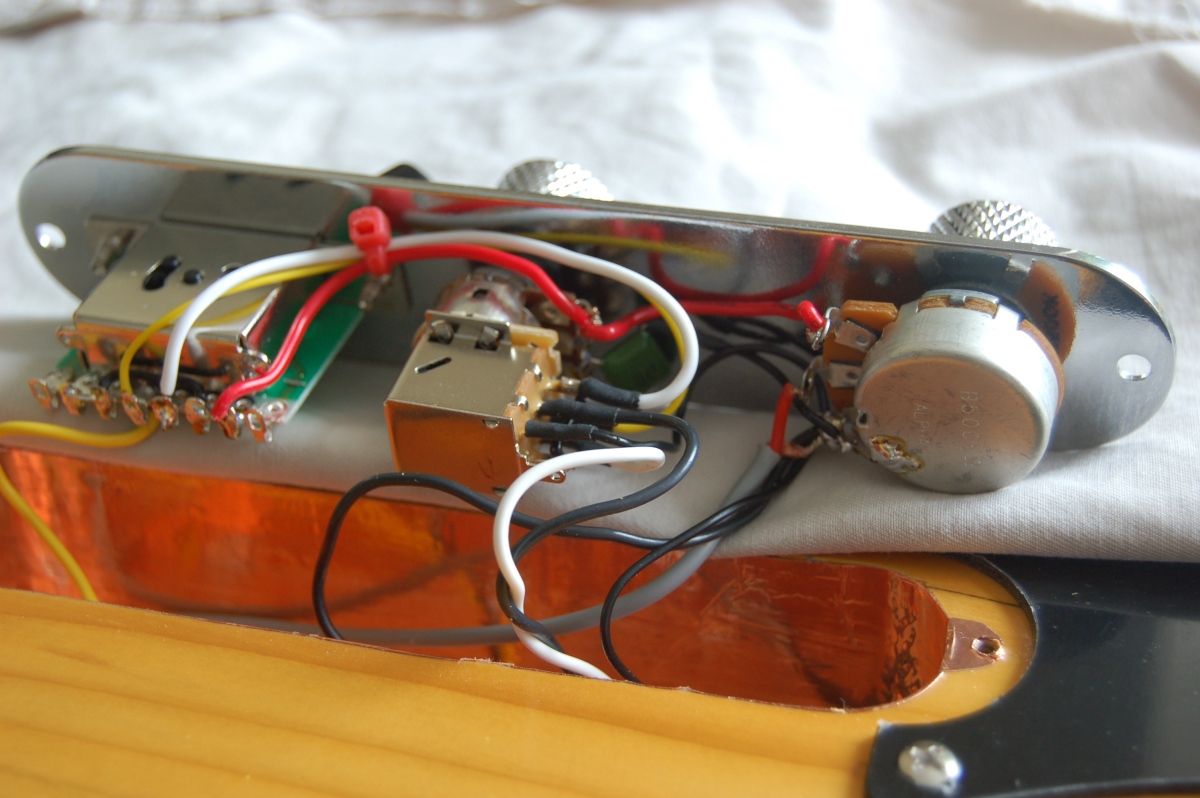
Pickups and controls
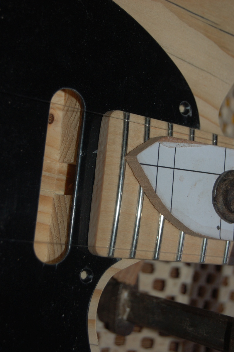
I needed to cut a notch in the pick-guard to accomodate my sticking-out truss rod adjustment nut so that I could get the neck on and off. The notch will still be hidden by the overhang.
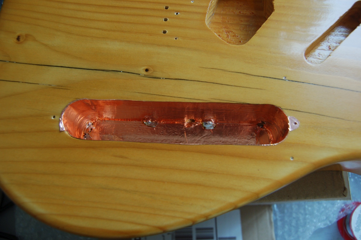
To finish the body, I shielded the control cavity. I didn’t do the pickup routs as I ran out of foil! (And there are reasonable arguments as to why it’s not really necessary)
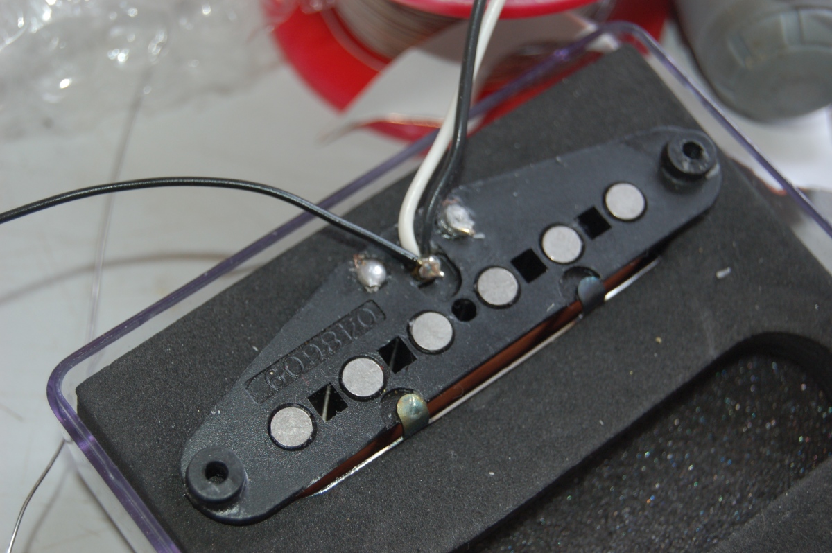
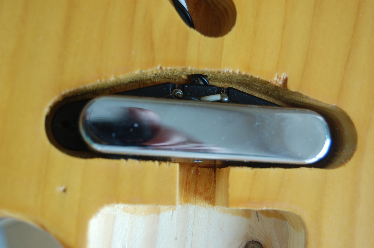
I’d picked up some some MIM pickups to use in the guitar, but I wanted to body mount the neck pickup and explore the options for out of phase wiring. I snipped the link on the back of the neck pickup and fitted a dedicated ground wire to the cover:
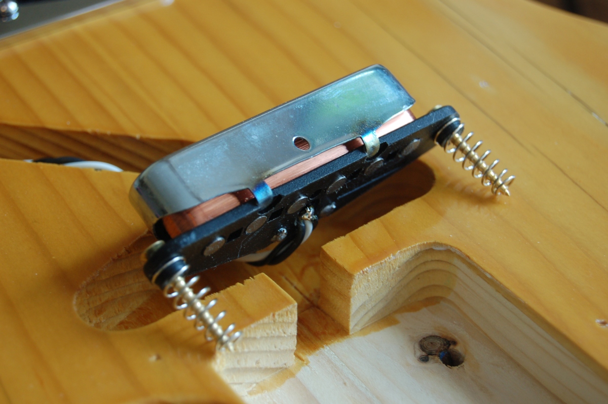
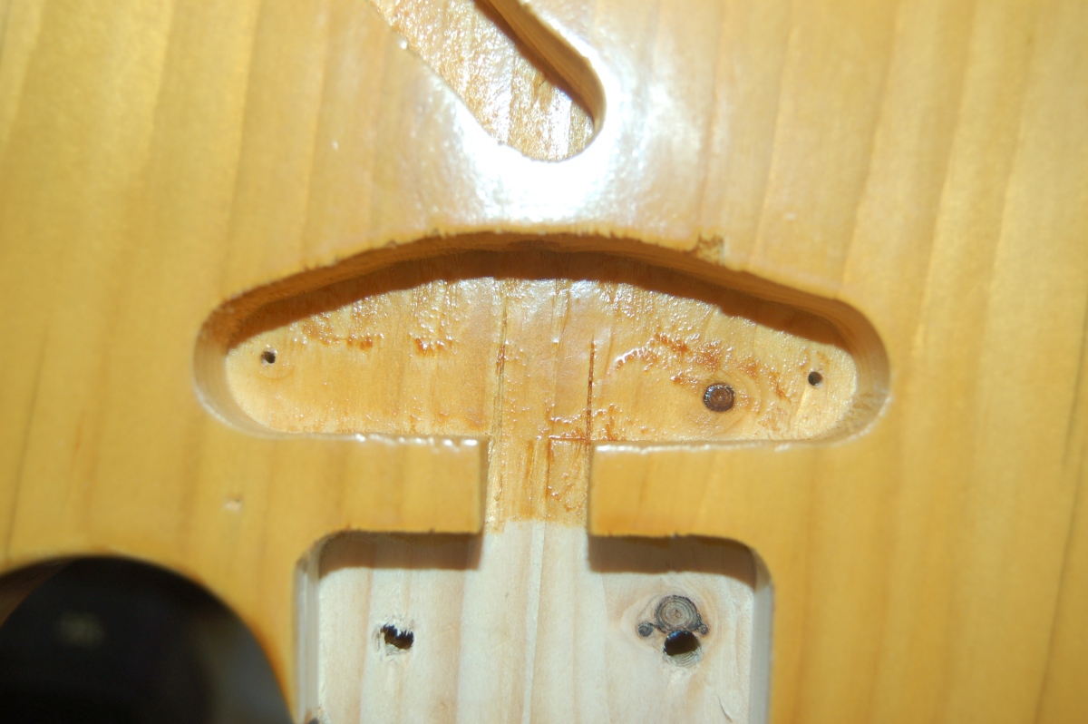
and drilled through the threaded mounting lugs to take wood screws and springs:
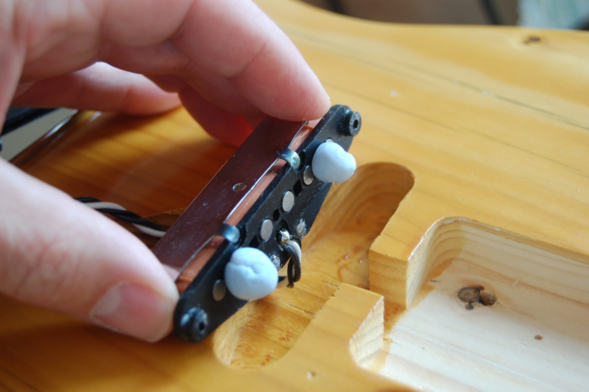
To get the pickup square in the pick guard, I put some blu-tac under the pickup and placed it loosely in the rout. I then fitted the pick guard and squished the neck pickup down so it was square, removed the pick guard and marked through the pickup mounting holes:
Bridge and pickup went on OK, and I wired it with a reversed control plate and a push-pull switch for the ‘series-out-of -phase’ wiring.