
When I reassembled everything, I noticed that the X axis ballscrew seemed to be bent – the ballscrew nut mount was flexing noticeably as the screw turned.
I took it out again and got it centred up in the lathe and while it had some runout, I didn’t think it was that bad (something like 1mm runout over ~400mm). Nevertheless, it seemed to be causing a problem, so I decided to try and straighten it.
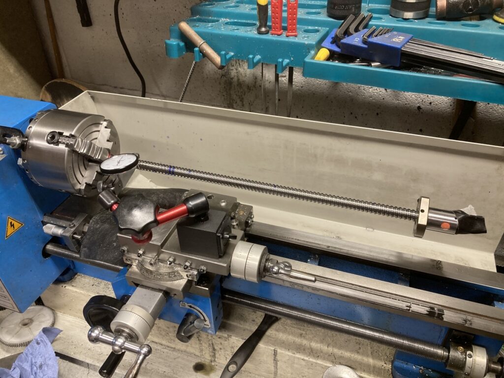
I set the lathe leadscrew to the same pitch as the ballscrew so I could run the DTI down the ballscrew thread and plotted the total runout along the length.
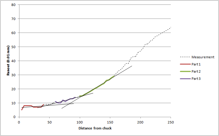
By plotting the runout, it was clear that it had a couple of kinks in it – a small one at about 40mm and a bigger one at 100 mm (both in the same plane):
I marked the position and direction of the two bends and clamped the leadscrew in the lathe chuck next to each mark in turn. By carefully leaning on the end of the ballscrew, I got rid of the worst of the bends and got it running reasonably true.
It certainly looked a lot better
It measured better, too.
When I put everything back together, the thing was still running out! (AAARGH!)
To cut a long story short, I eventually traced the problem to the way that the thrust bearing was mounted on the ballscrew.
The bearing arrangement is similar to this one:
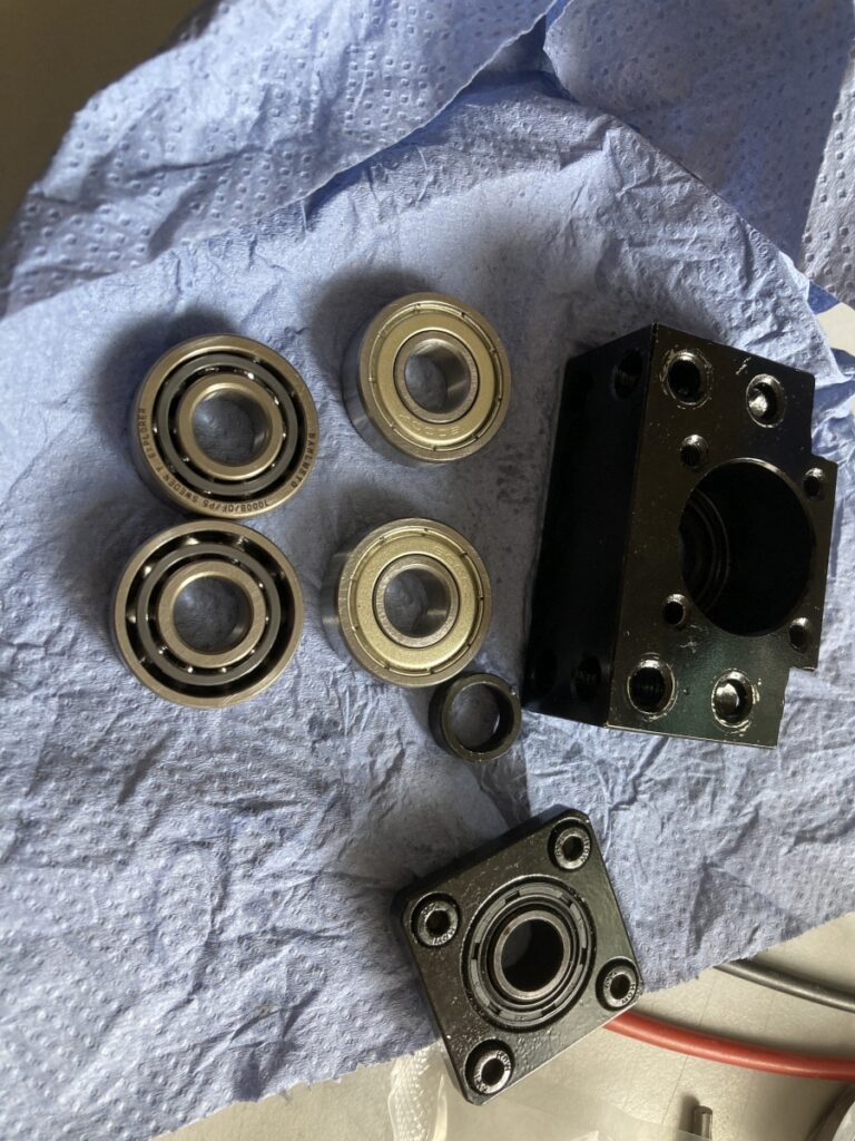
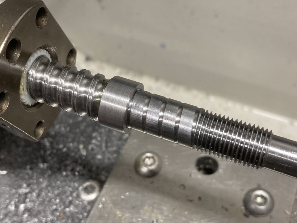
There’s a couple of back-to-back angular contact bearings (not the plain ones in the photo) with a short spacer either side that mounts on the end of the ballscrew. The end of the ballscrew is machined down (by the manufacturer) to take this assembly and it all gets clamped into place by a locking nut. What was happening was that the spacer was a bit of a sloppy fit, and rather than being supported evenly on the (small) machined shoulder, it was resting on a single point where the ballscrew ‘thread’ finished – Tightening the nut was putting a bending force on the shaft and causing it to deflect. Note that I was only tightening the nut as much as I could whilst holding the 12mm diameter ballscrew with my other hand – so not very tight at all.
Runout with the original spacer and the clamping nut tightened:
With the clamping nut loose, the runout was much less:
Once I’d figured this out, it was easy to make a new spacer that was a tight fit on the end of the ballscrew (loctited in place for good measure) so that the load would be transferred evenly to the ballscrew.
Runout with the new spacer and the nut tight:
Once fitted back to the machine, it was OK. I may have to do the same to the Y and Z leadscrews at some point, but for the moment, the don’t seem to show the same problem.