
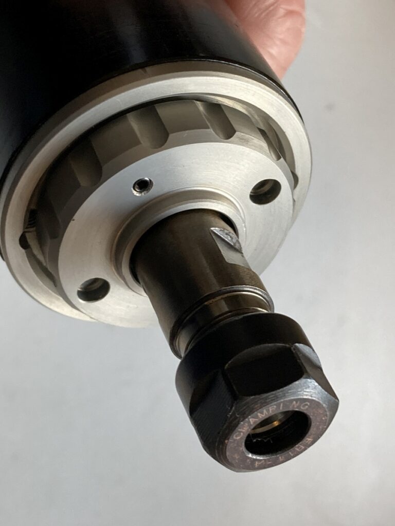
Right then, that spindle.
It was a bad choice.
When experimenting, trying to find cutting depths and feeds that worked, I became suspicious that something, somewhere wasn’t right.
I went through the machine, looking for backlash, play or loose fasteners, but I couldn’t find anything amiss – everything seemed tight. I then started clamping an indicator to various places to see how much they deflected and eventually found that firm hand pressure against the ER11 collet chuck would move it by ~0.1mm the spindle itself was only moving by ~0.01mm.
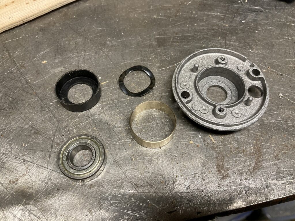
This led on to the discovery that the spindle bearings were a) weedy and b) wedged into the end cap with a rubber boot!
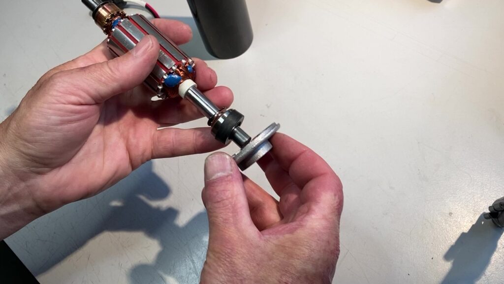
At this point, I should have cut my losses and found a different spindle. But I had a couple of spare angular contact bearings, and there seemed to be a lot of fresh air inside the front of the spindle housing…
I drew up the original design in F360:
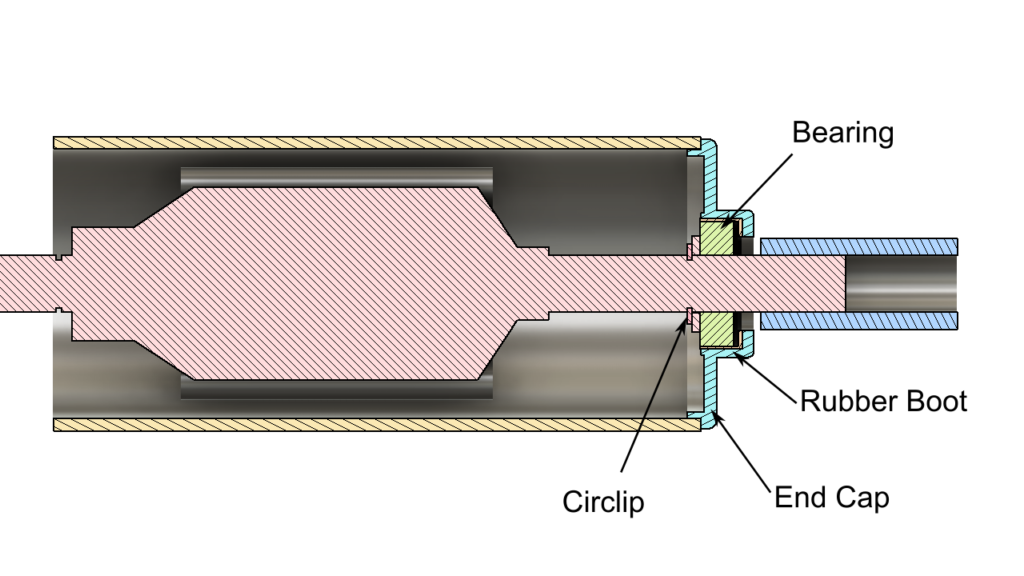
And indeed, as it seemed, there was enough space to fit in a new, much deeper end cap containing some more substantial bearings.
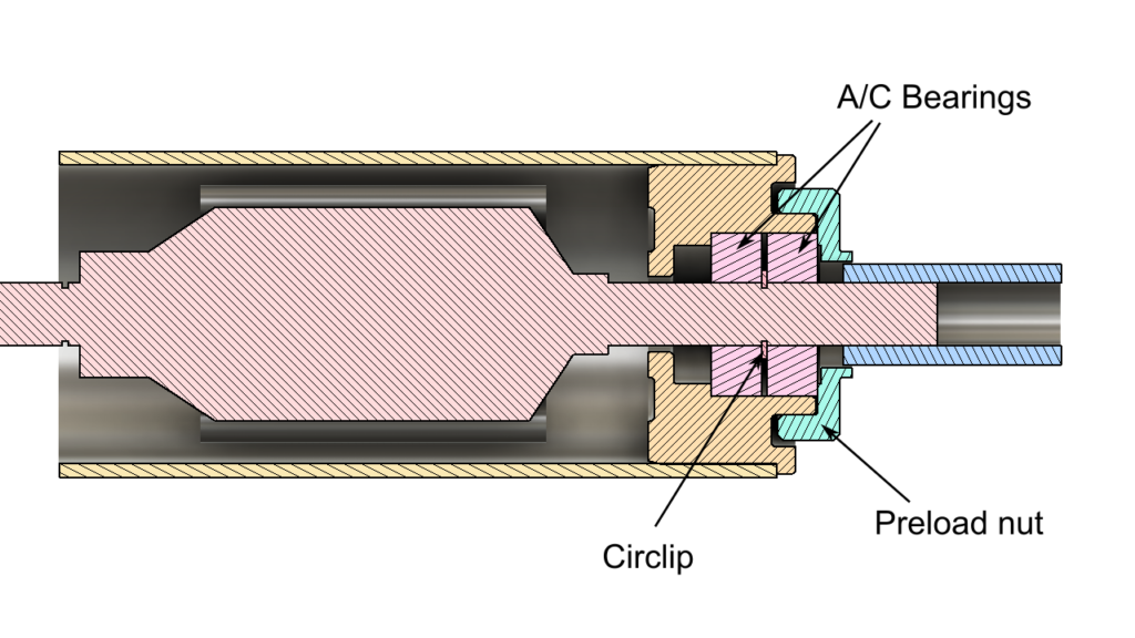
The only way I could think of to locate them axially was by sandwiching the original circlip (or something in its groove) between the pair of angular contact bearings that I had:
I had a suitable chunk of aluminium already, so the only thing I would be wasting was my time…
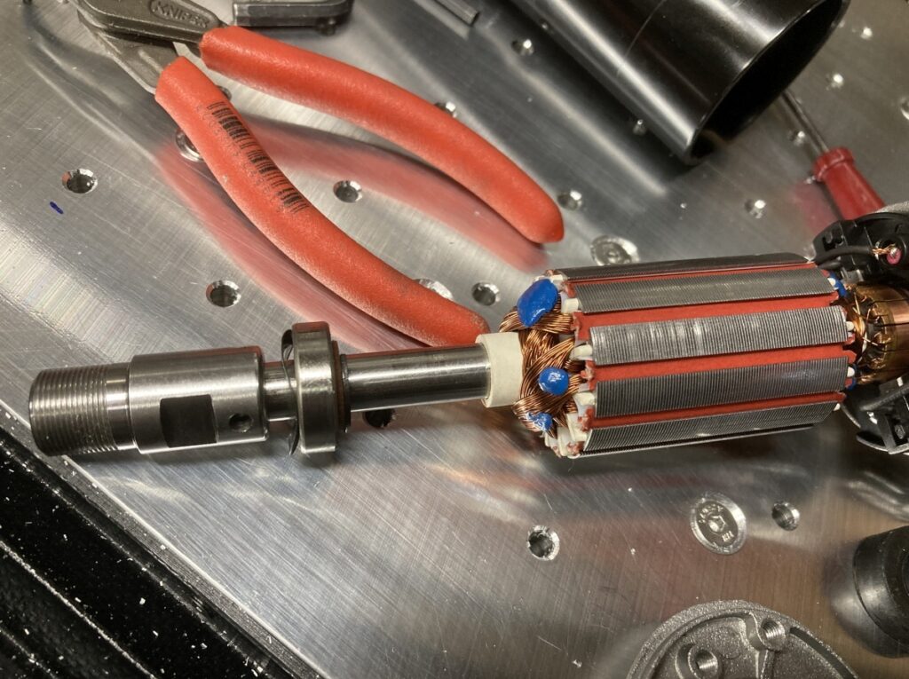
I needed to get the ER11 chuck off the old spindle to get to the bearing. My word, it was on tight! I had to heat it and jack it off the shaft with a bolt through a nut held inside the ER11 collet nut. It was that tight that I stripped the threads of a normal M6 bolt and had to use a HT cap screw one instead.
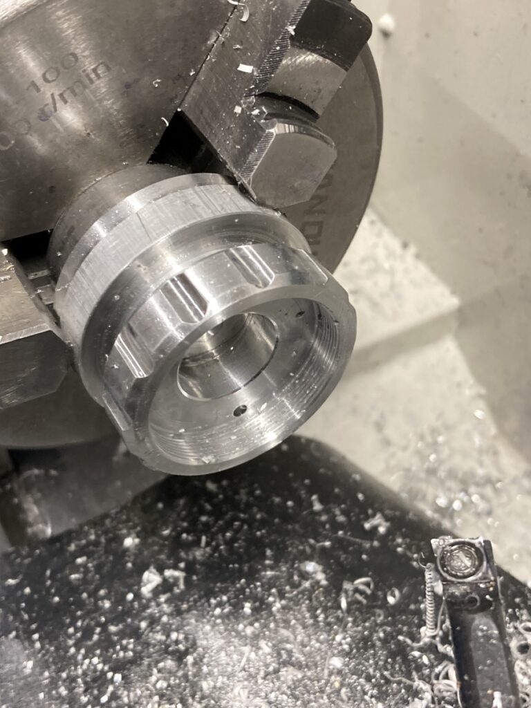
The new housing was just turned up on my lathe
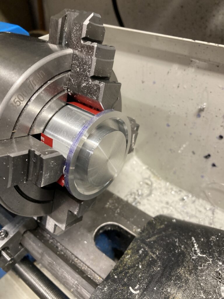
(I milled a locating slot in it using my toolpost spindle before cutting it off the stock)
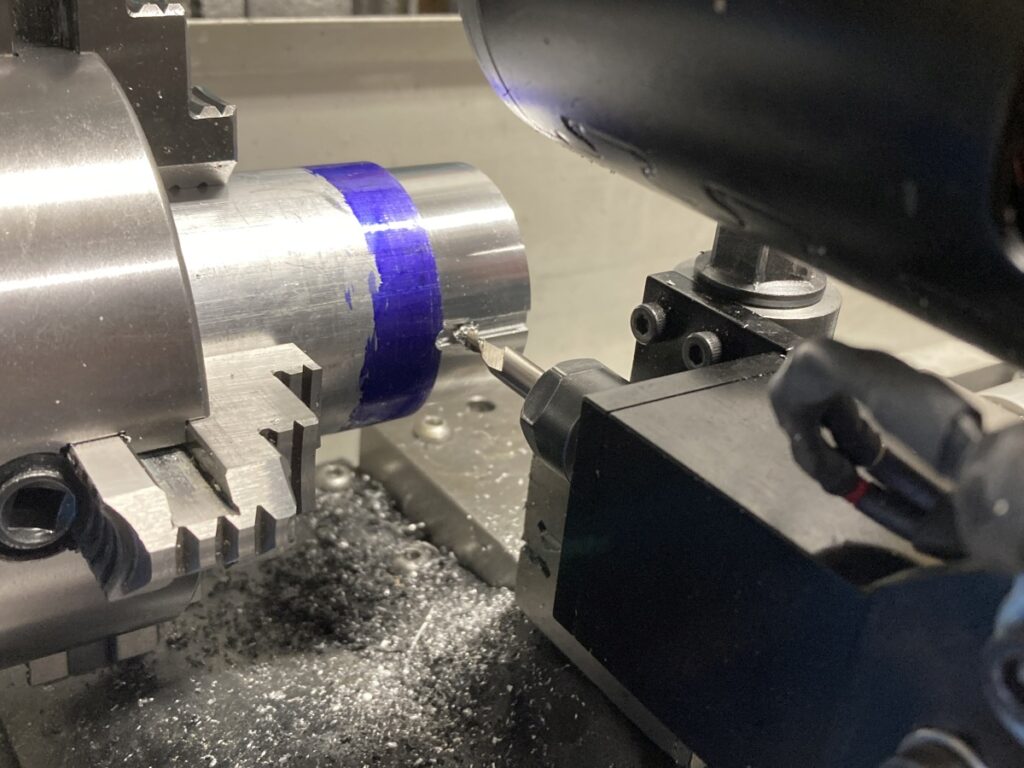
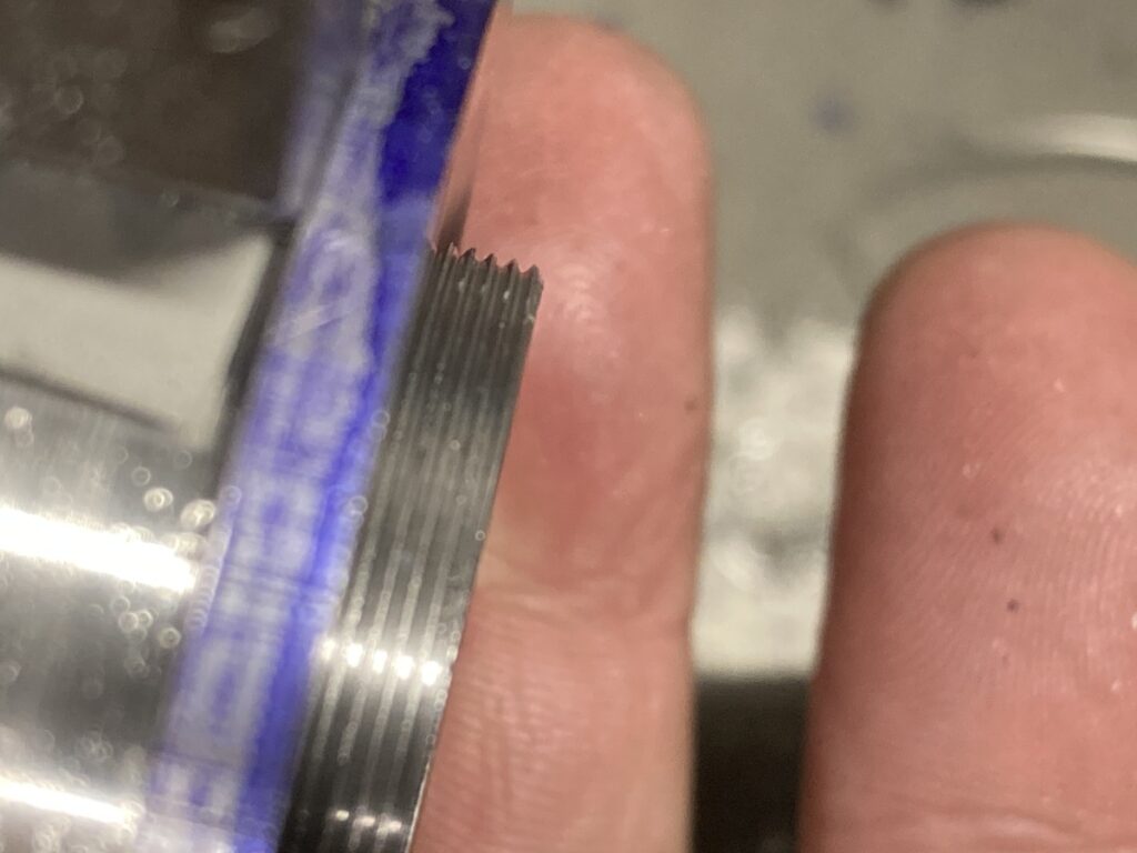
I didn’t have a thread cutting tool small enough to fit into the recess in the front of the housing to cut the external threads for the preload nut, so silver soldered a broken M4 tap (I make my own 😉 ) into a piece of bar and ground off all but one tooth – voila: a full form 0.7mm pitch thread cutting tool
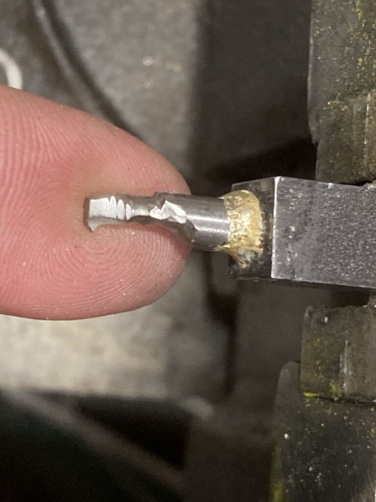
It worked quite nicely!
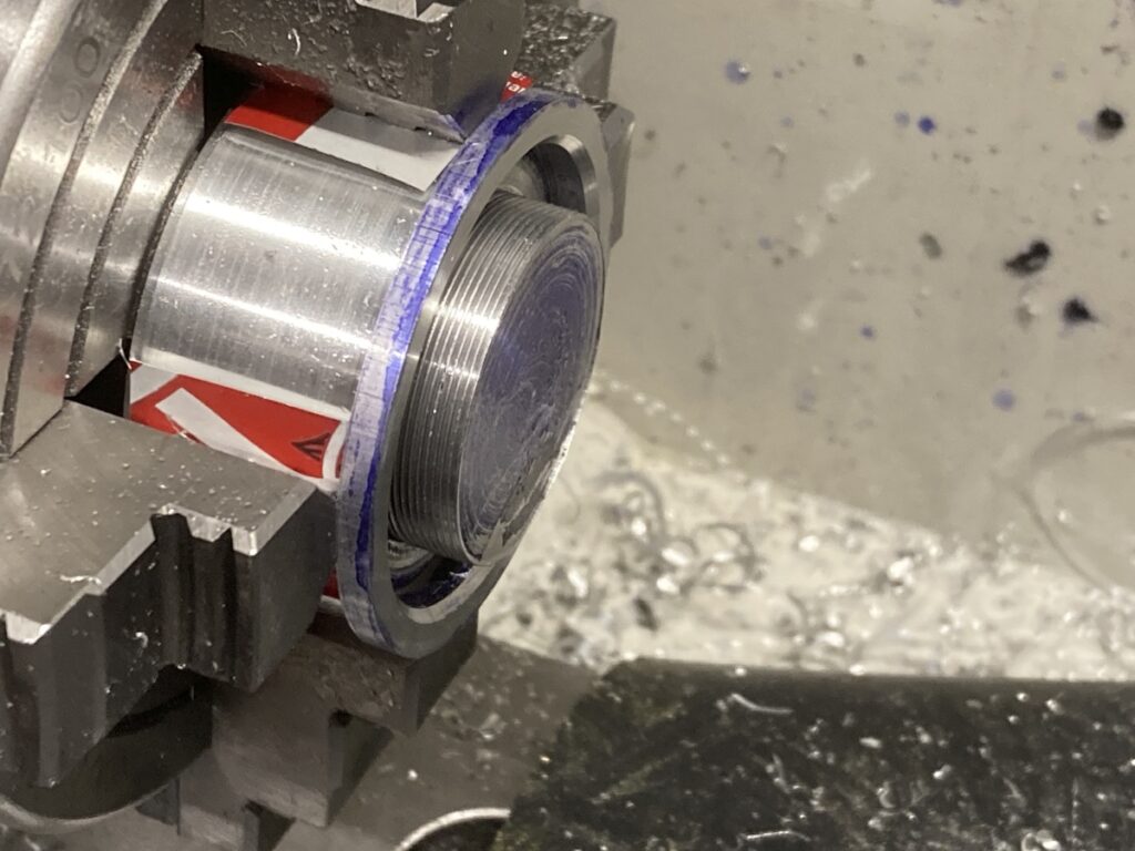
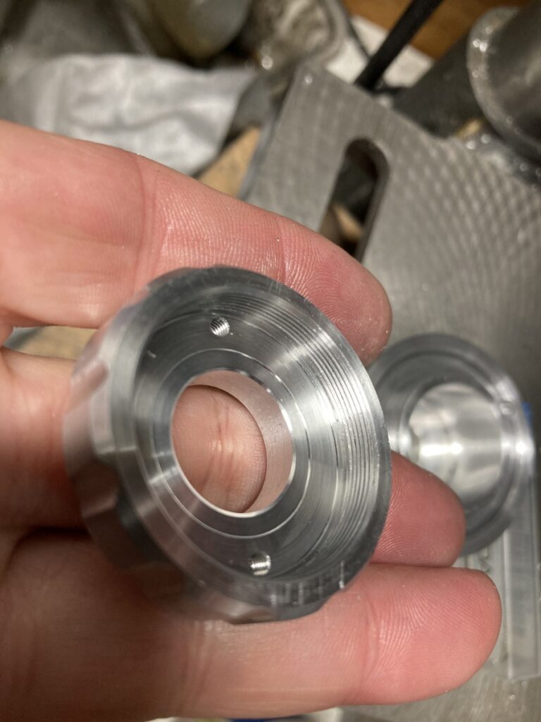
I made the preload nut and did the internal threading with the same tool:
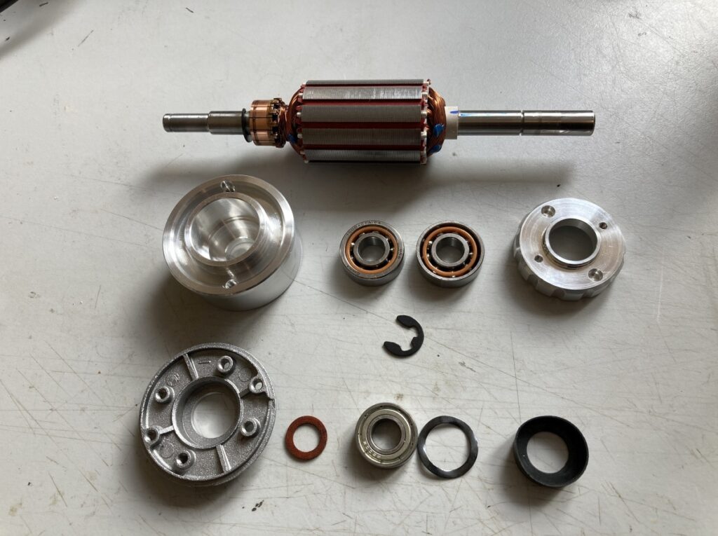
The new bits and the old bits side by side
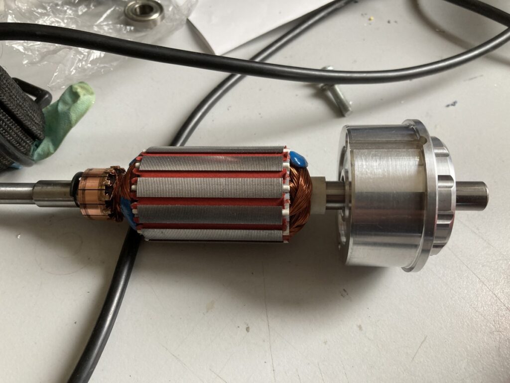
New bits assembled to the armature
All I had to do now was get the ER11 chuck back on. I thought I might get away with being civilised – I heated the chuck and tried to press it onto the armature using my lathe tailstock. It didn’t want to know at all. I eventually resorted to brute force, and battered it back on with a hammer.
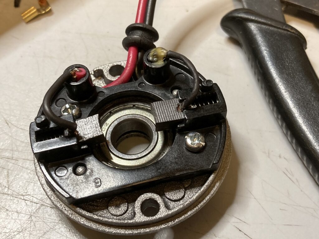
In the process of replacing the chuck, I managed to smash up the brushes (I found out when I tried to power it up. There was a bang and a flash and all the lights went out…) Spares brushes are available from China with 3-4 weeks shipping. As I’m impatient, I ordered something close and sanded them to fit. While I was in there, I made a brass sleeve to replace the rubber bush on the rear bearing.
Perhaps unsurprisingly, the collet chuck didn’t run awfully true afterwards (maybe +/- 0.05mm). I had marked the orientation of the chuck wrt the shaft when I took them apart, but my marks were inside the motor when I put them back together, so I couldn’t see them! (I don’t know if it would have made much difference.)
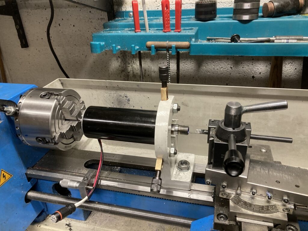
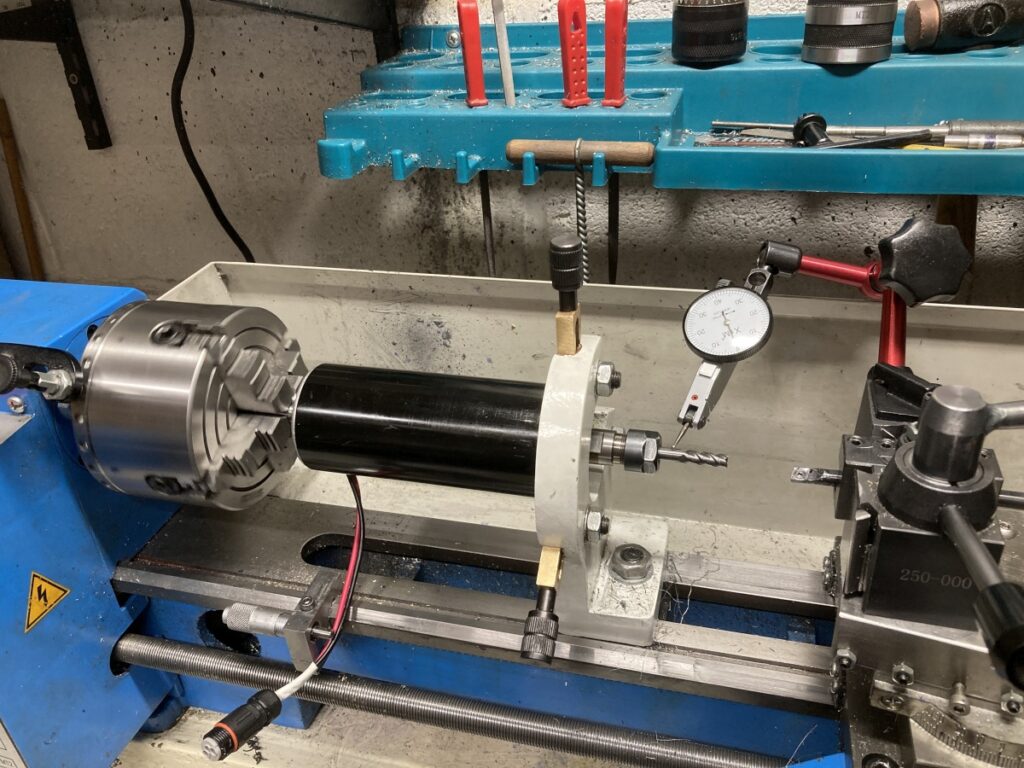
Anyway, it wasn’t coming apart again, so any improvement would need to be made with the spindle assembled. I started thinking about how to set it up in the lathe to be able to re-cut the ER collet taper and realised that if I could support the spindle housing, I could true up the collet taper with it running in its own bearings. My fixed steady was just big enough to go around the new preload nut:
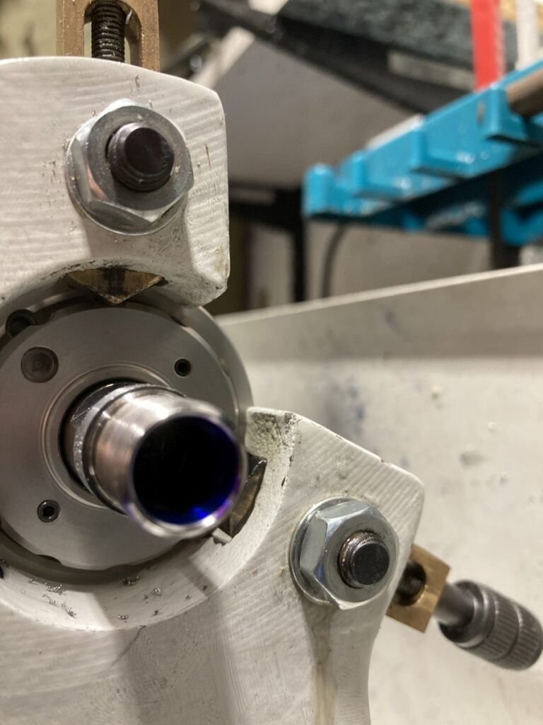
With everything running true, I clamped the steady onto the spindle and re-cut the collet taper
The best I could get was +/- 0.01mm runout when measured on the shank of a tool clamped in the collet. (I don’t have any ‘before’ measurements to compare it to.)
I had measured the stiffness (compliance??) of the spindle before I took it to bits, and while there was an improvement afterwards, it was not as much as I had hoped – I was measuring ~800 N/mm before and ~2,500 N/mm after (measured at the top of the collet chuck). The stiffness of the spindle body measured next to the chuck is ~6000 N/mm – obviously, these will be a lot lower down at the tip of the tool.
It is also very temperature sensitive – the bearings tighten up when cold, so I need to run the spindle for a few minutes to warm it up before trying to cut anything. (I probably shouldn’t have used aluminium for the bearing housing)
I was hoping to be able to turn a sow’s ear into a silk purse, but I think all I’ve achieved is to make a slightly better sow’s ear.
I’m running with it for the time being.