I was hoping to find some 120 mm wide, thick wall rectangular hollow section to make the gantry, but all I could come up with was some 100 x 50 x 3. Thinner than I wanted, but I thought it might be OK if I welded on some thicker pads where the linear rails would fit, and possibly filled it with sand, or something to stop it ringing if that proved to be a problem.
Anyway, I got out the welder…
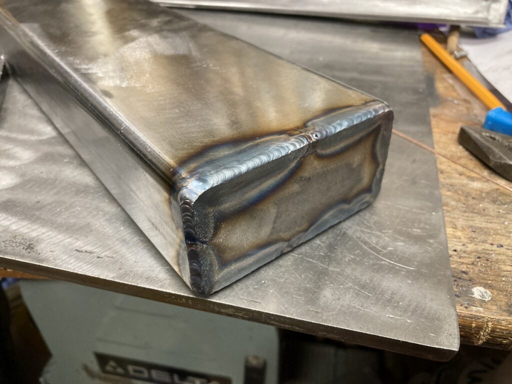
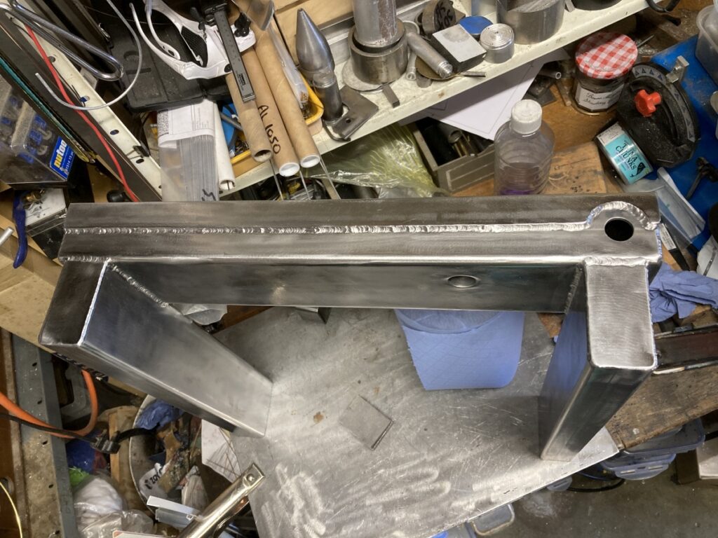
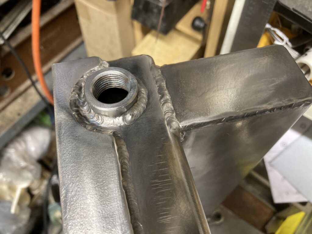
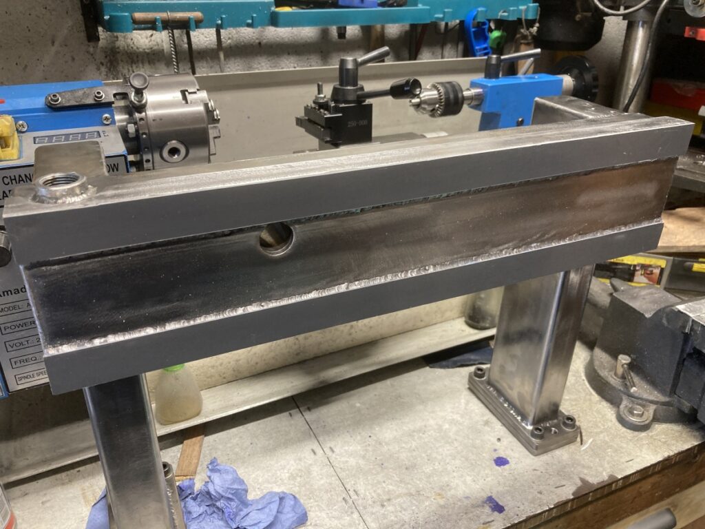
Capped off the the ends (the right hand end has a doubler welded inside the bottom of the section to drill and tap into for the X axis leadscrew mount at some point in the future). This sort of thing is coming out neater since I started tacking the edges rather than the corners.
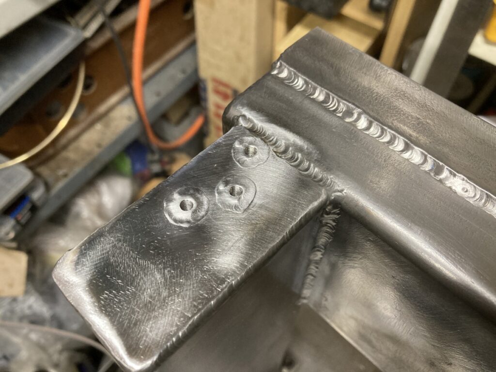
I realised that I’d need to be able to access the screws holding the X/Z plate onto the Z axis somehow when the thing was being assembled, so after some CAD puzzling, I ended up with a little tunnel through the main gantry:
I tacked some 25 x 25 x 3 angle to the front to square up the corners and give something to secure the linear rails to.
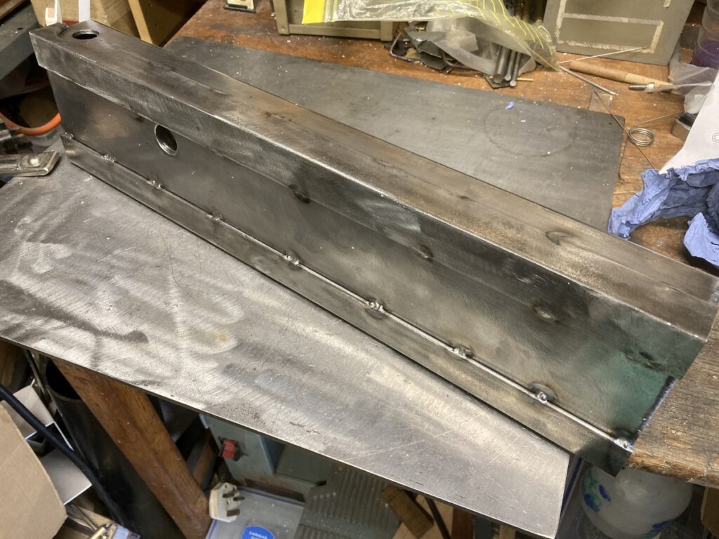
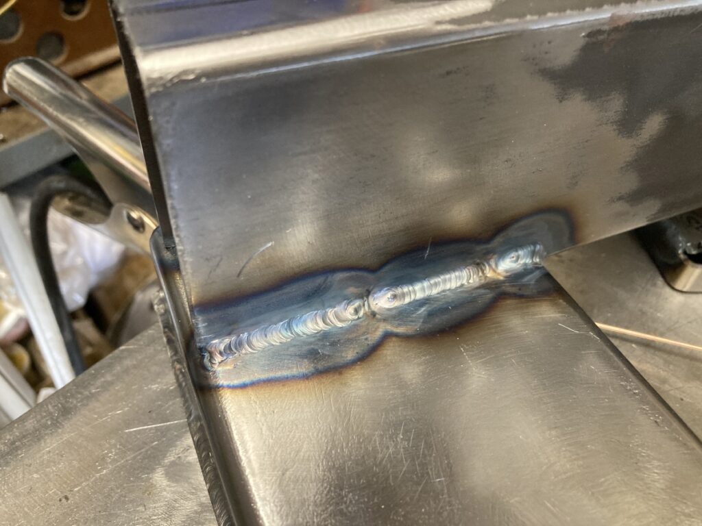
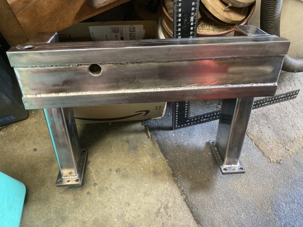
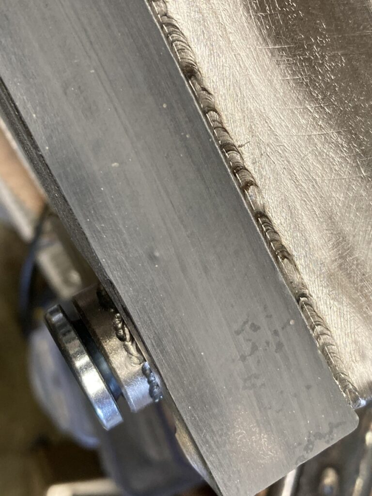
I was only going to stitch weld it at ~25mm intervals, but I messed up my marking out and ended up with the tack welds in the spaces between stitches – it looked awful so I filled in the blanks and they ended up fully welded.
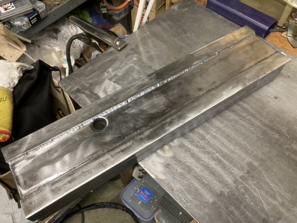
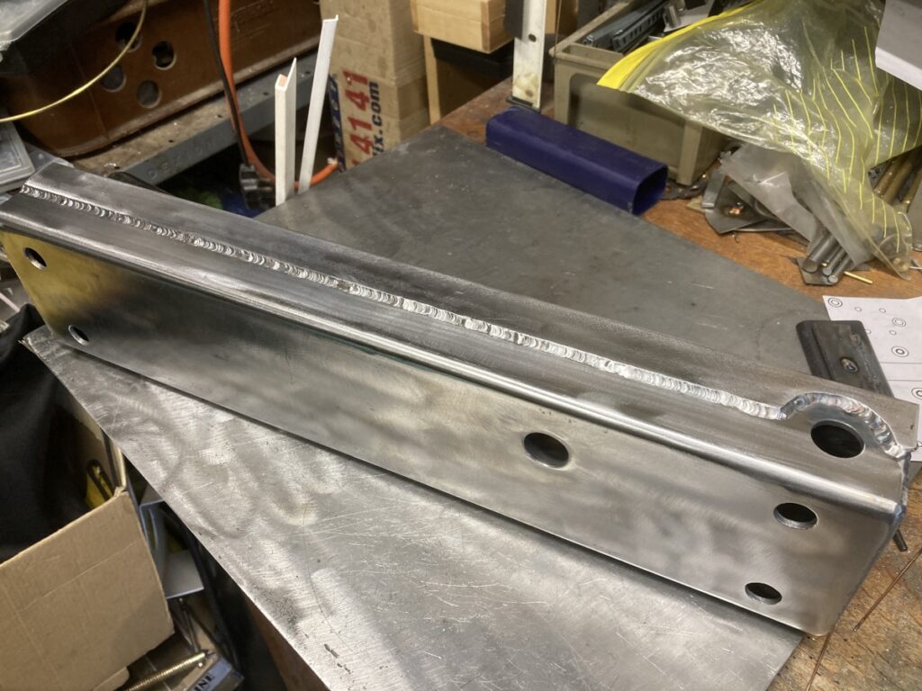
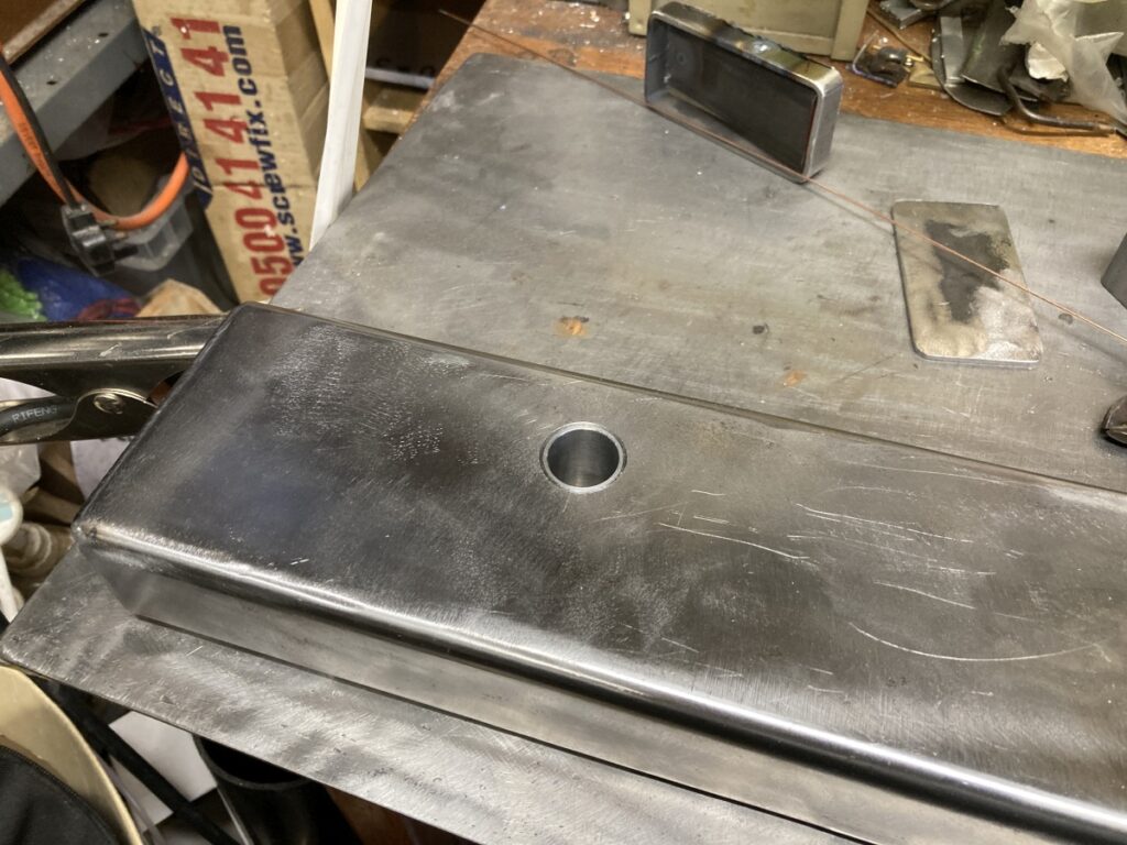
The hole in the top is there in case I decide to try filling the fabrication with something (sand) at some point in the future, and the extra holes at either end of the face are to allow that filling to flow into the uprights.
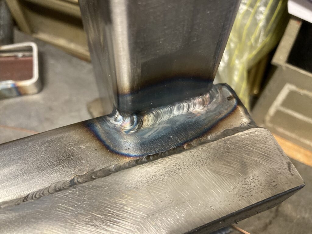
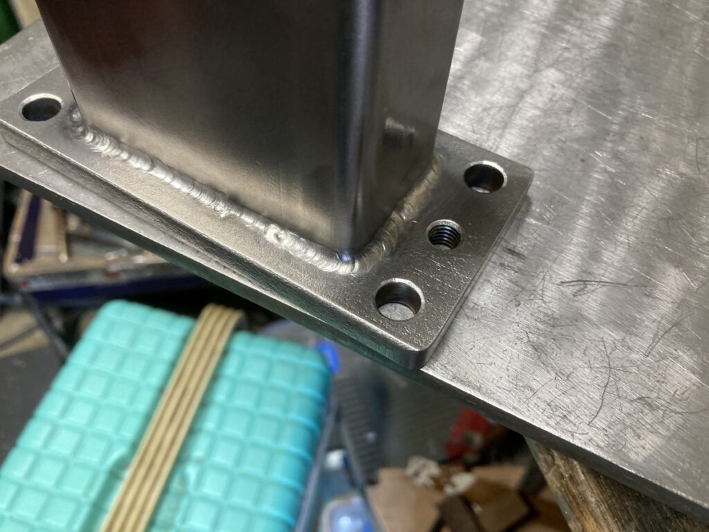
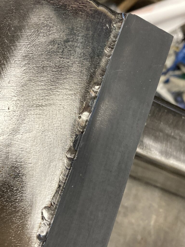
The best I could scrounge for some uprights was some 80 x 40 x 3 which were notched to fit around the cross beam (I had it in my head that the joints would be more rigid if they spanned two faces of the box)
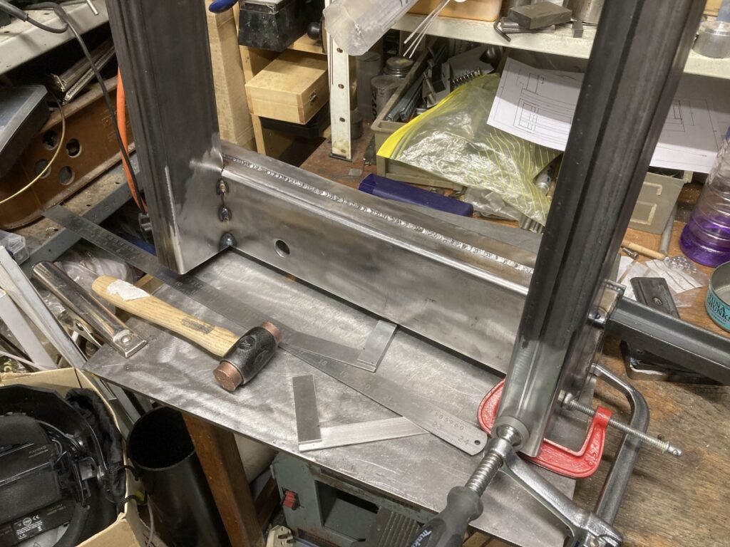
I seam welded them to the gantry and also capped off the tops – I wanted them to be water (or at least sand) tight
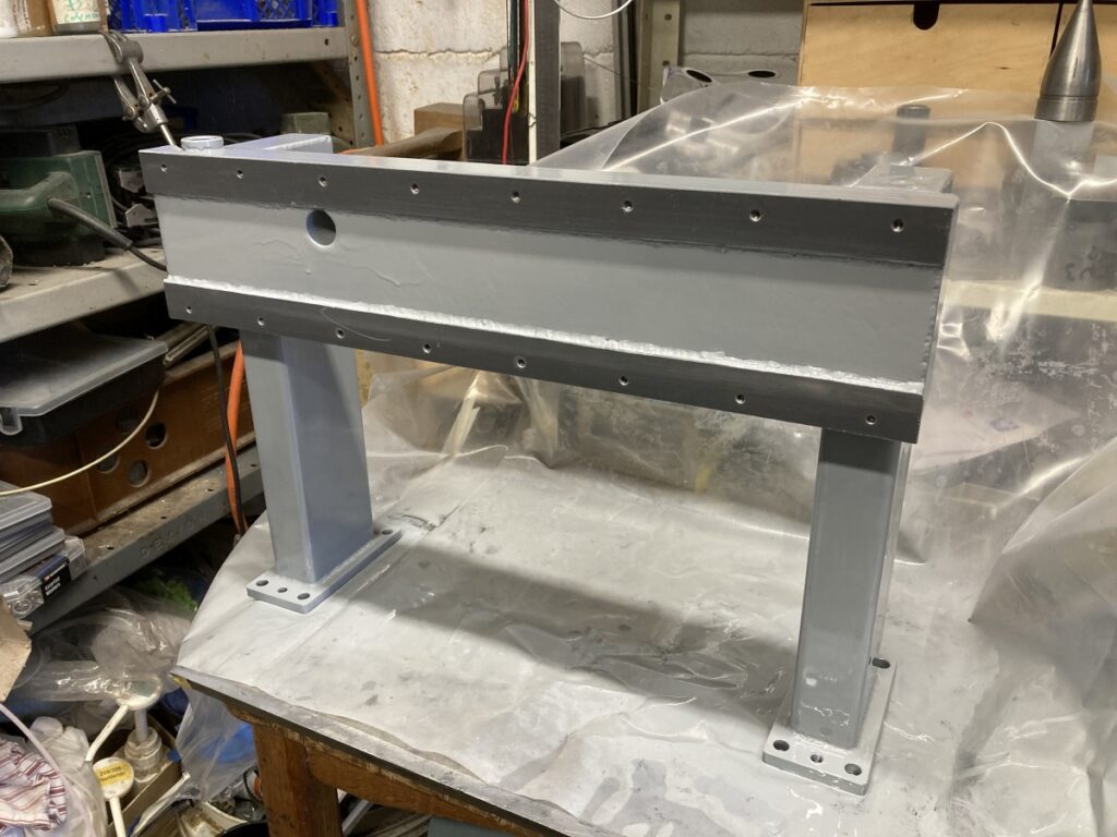
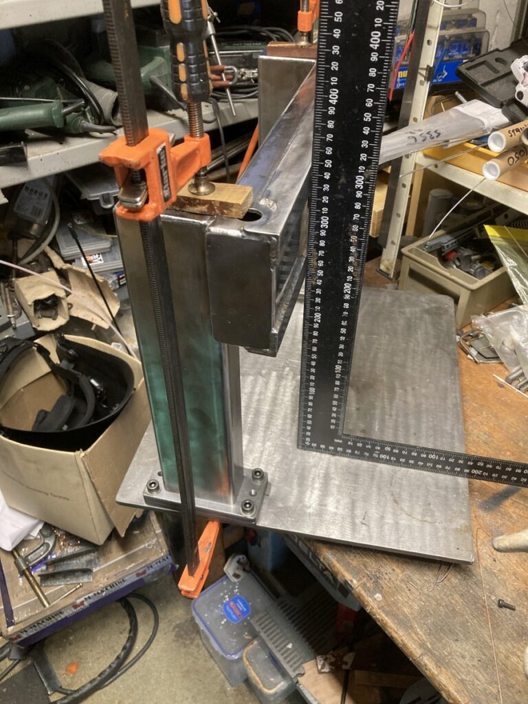
Then stood it up for a look
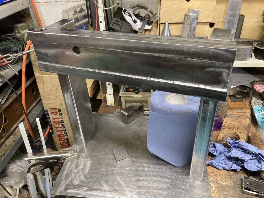
I hadn’t designed the bottom half of the machine at this point, so just made some flanges that could be welded to whatever I ended up with later:
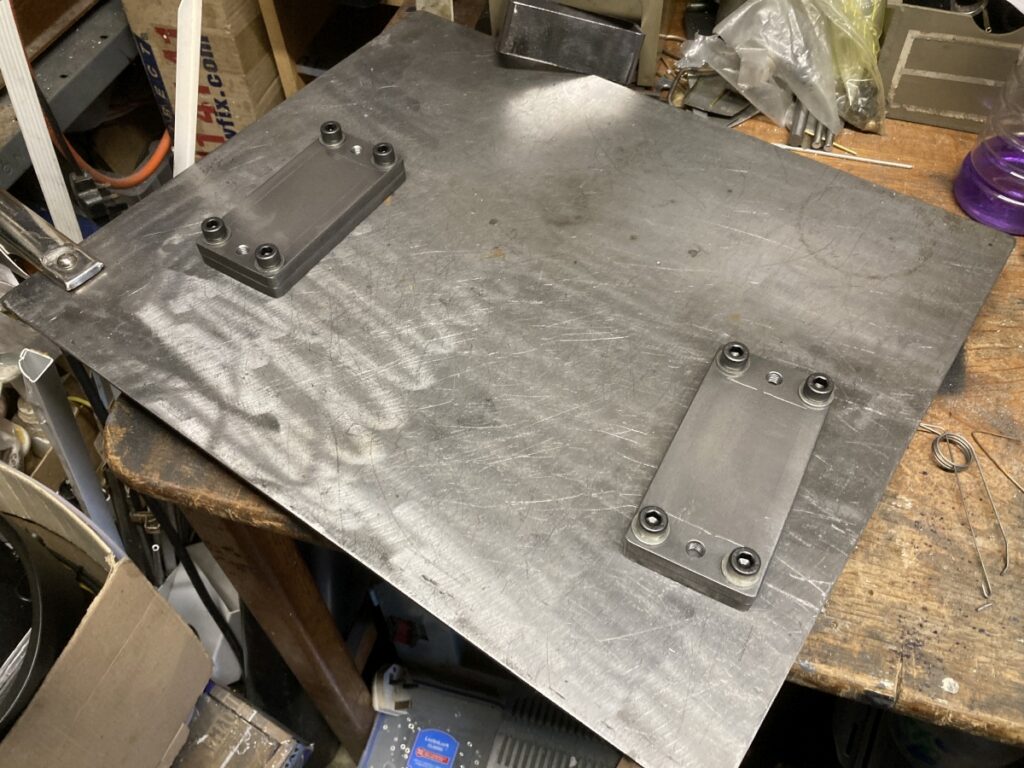
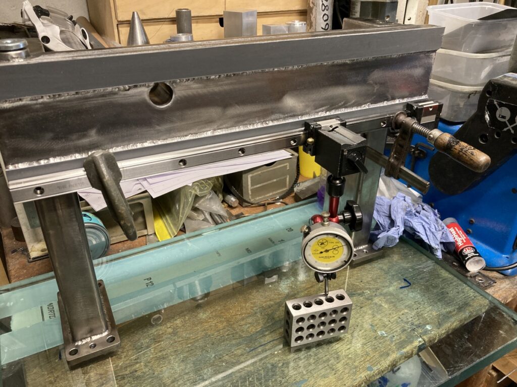
After all of that, the front face was only 0.3mm out of plane (judged against the glass plate).
I intended to use epoxy to accurately level the linear rail beds and get them co-planar, so I needed to finish off all the welding on the gantry before I could do that.
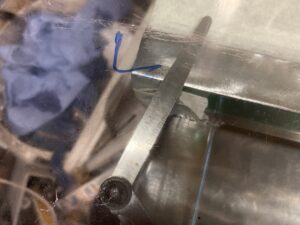
A bung for the sand filler (yes, it is awfully undercut – must do better! )
And tapped blind inserts wherever I wanted to bolt something to the gantry (so if I could fill it with something and not have it leak out of the bolt holes).
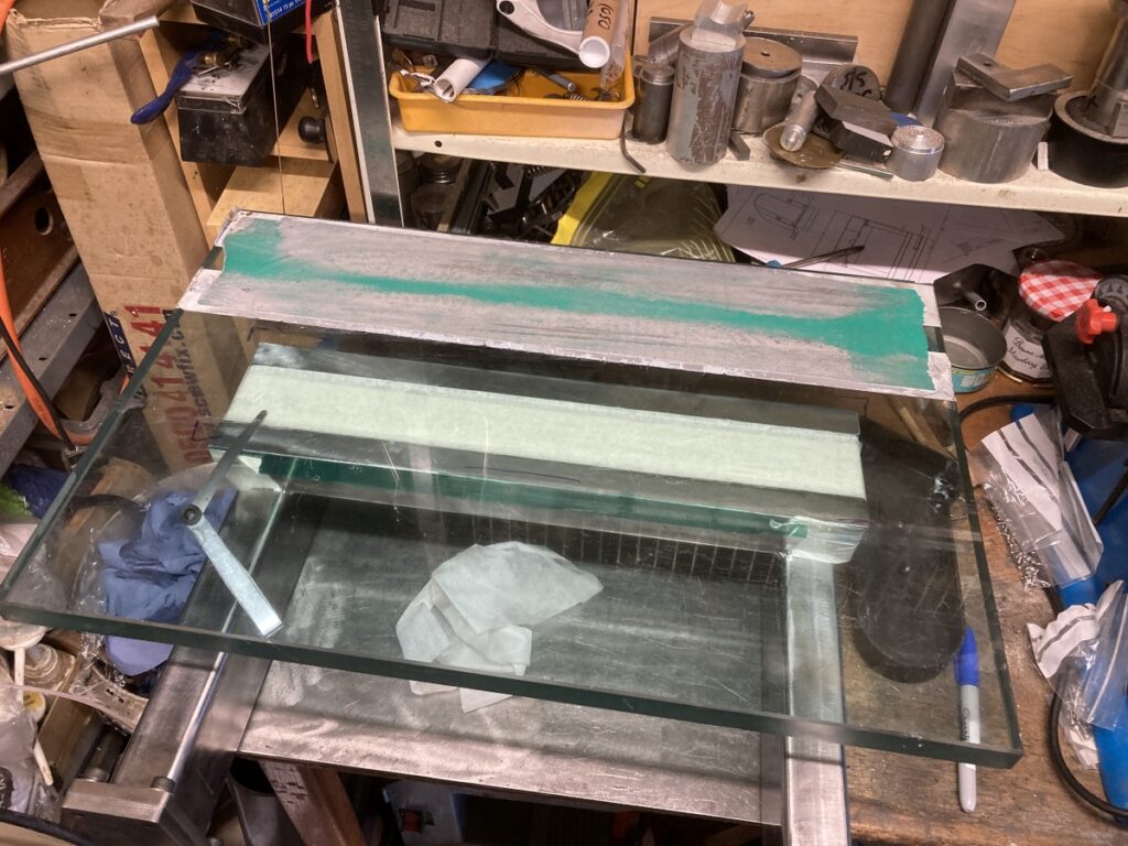
After that, I masked it off, got it set up nice and level, and then slathered the 25mm wide pads with slow setting epoxy.
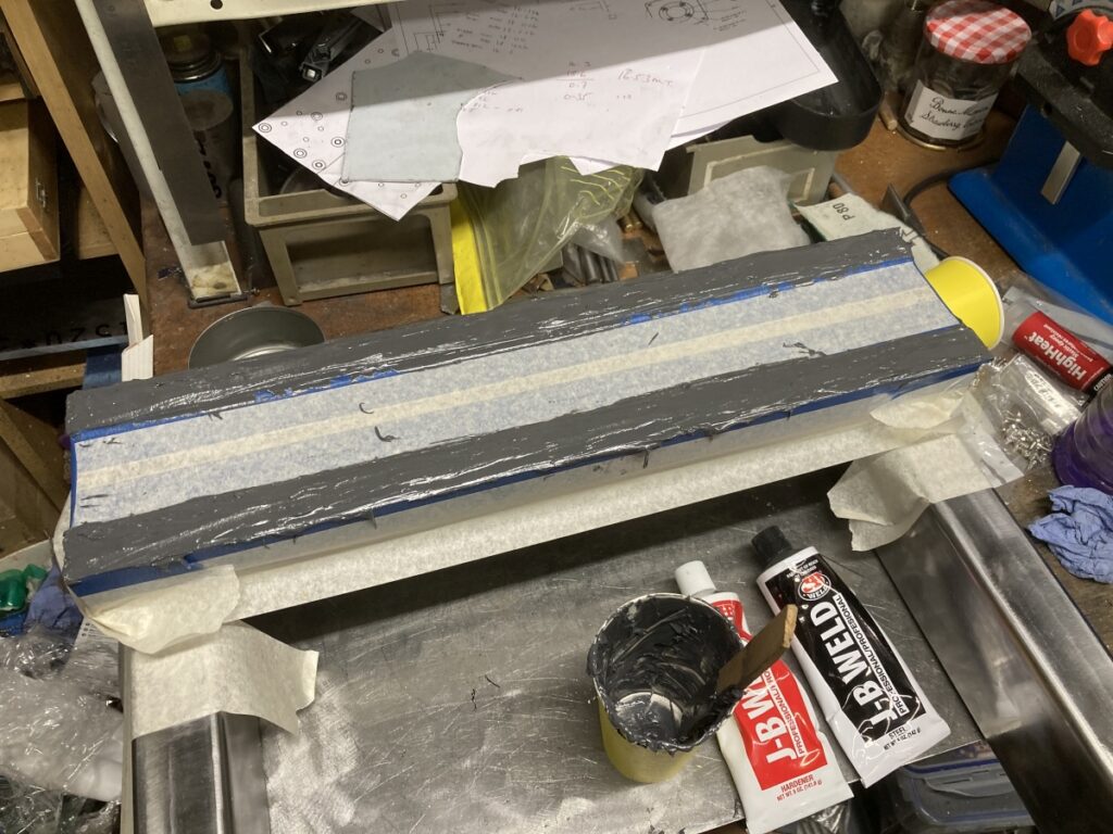
The glass plate, with a layer of cling-film over it, was carefully lowered onto the epoxy, squidging it out:
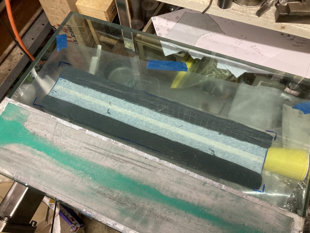
Once I was reasonably confident that it wouldn’t slide off onto the floor, I walked away and left it for a day.
Getting the glass to release was a bit of a battle – I thought that they were permanently joined at one point, but it eventually came apart.
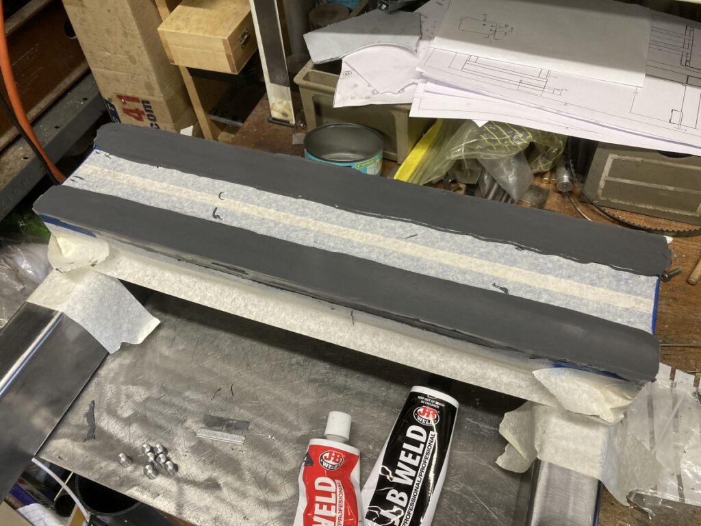
After a clean-up, it seems to have worked quite well:
The metal was grinning through the epoxy on two opposite corners, so I think that the layer is as thin as it could be.
I could then set one of the linear rails up straight and parallel using the glass plate as a reference and mark, drill and tap for the securing screws.
I got it straight to within about 0.01mm to the glass plate which I was reasonably happy with – I’m not sure that the glass plate is that accurate.
With one rail set, the carriage was used to get the second rail parallel
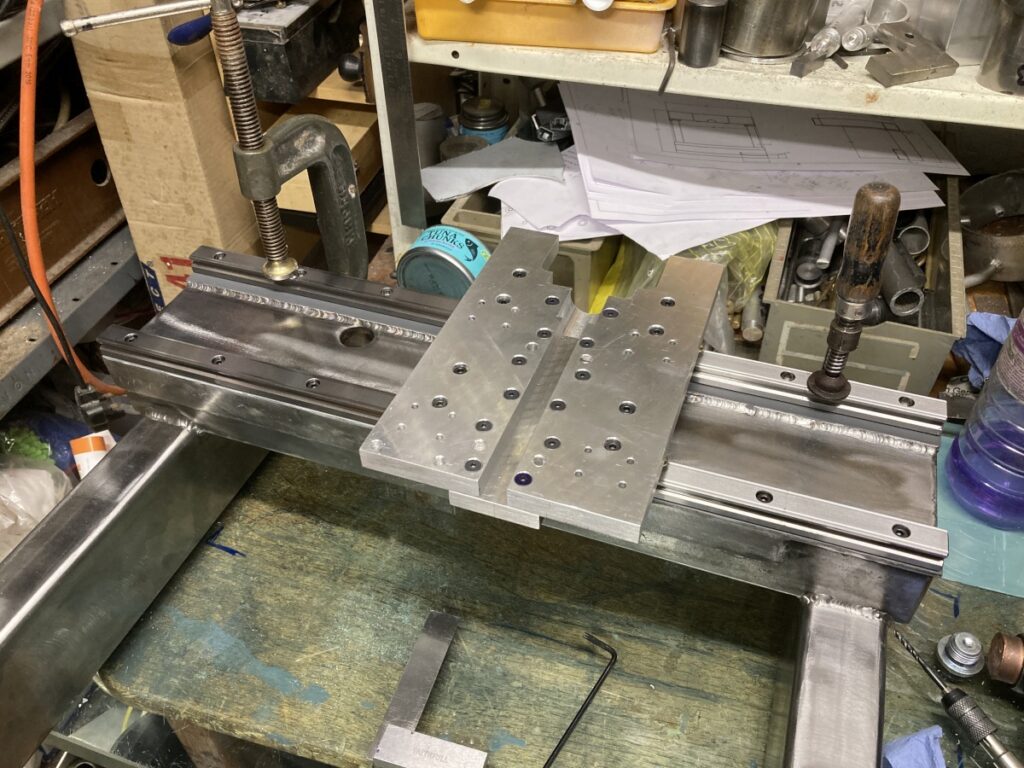
Once all the holes were drilled and tapped, I could indulge in a test assembly
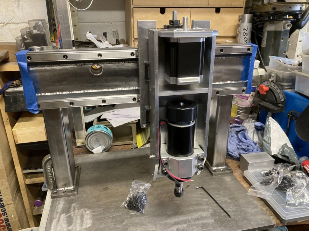
All seemed to be working as it should, so I gave it the world’s worst paint job and went on holiday for a few weeks.