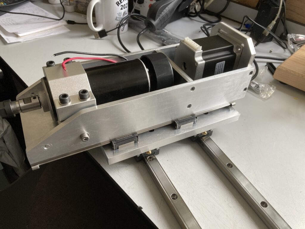
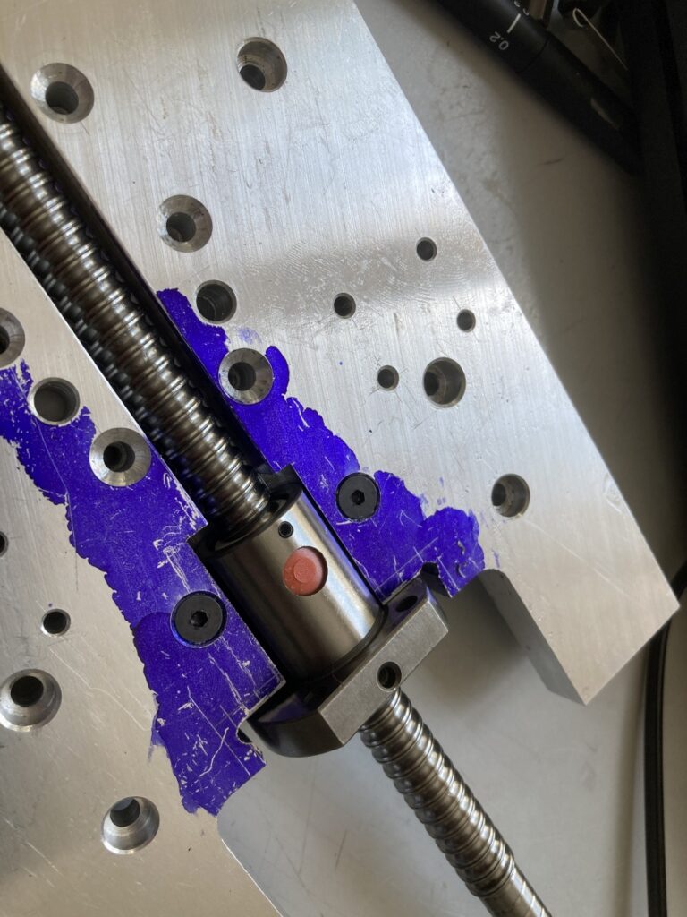
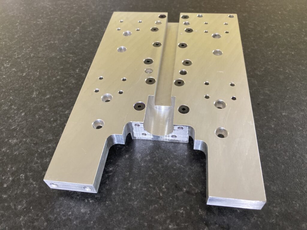
This plate connects the Z axis to the X axis on the gantry. The Z axis linear bearing cars fit on one side, and the X axis bearing cars fit on the other. It also holds the nut for the Z axis leadscrew.
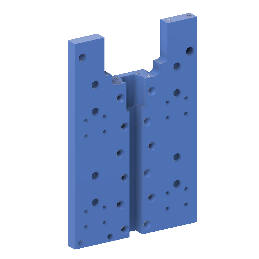
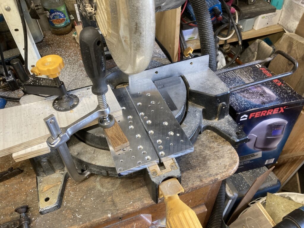
To try and keep things as compact as possible (and minimise the overhang of the Z axis), I needed to recess the Z axis leadscrew into the carriage. Instead of trying to machine it out, I made the carriage out of a couple of layers of aluminium tooling plate. The front plate was marked out and drilled with the rear plate screwed and dowelled to it. After drilling, a section was sawn out of the middle of the front plate to create a channel for the Z axis leadscrew.
I got some suitable offcuts of cast aluminium tooling plate from ebay – 12mm for the sides and 10mm for the bridging piece. (The faces of tooling plate are machined accurately flat and parallel, so should be suitable for mounting the linear bearings without needing any further machining.)
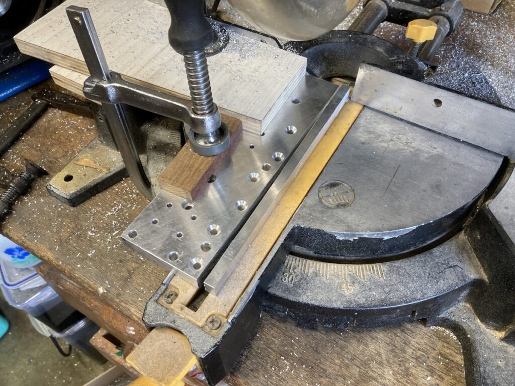
The two halves were marked out and drilled as one piece to try and keep them as accurate as possible. The bridging piece was also match drilled to the two halves while they were still in one piece, and a couple of dowels were also added to try and preserve alignment.
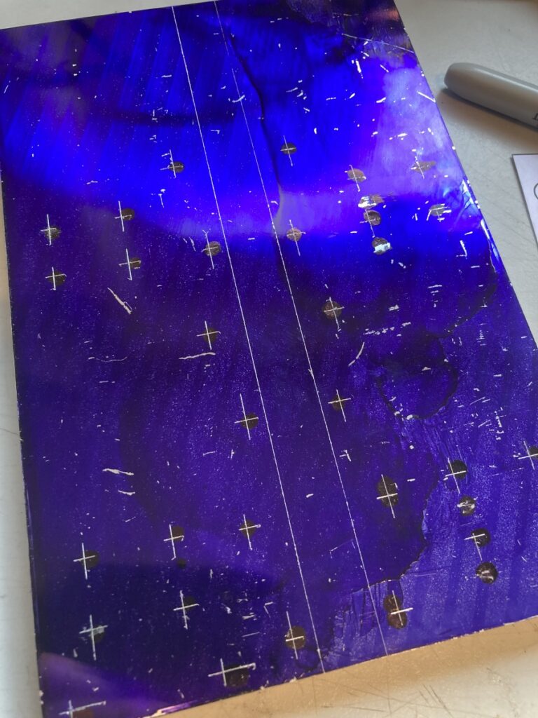
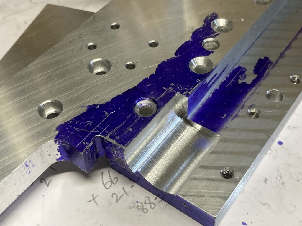
After drilling and counterboring many holes, the two halves were separated and cut down to create clearance for the Z axis ballscrew. (The mitre saw has a multi material blade fitted.)
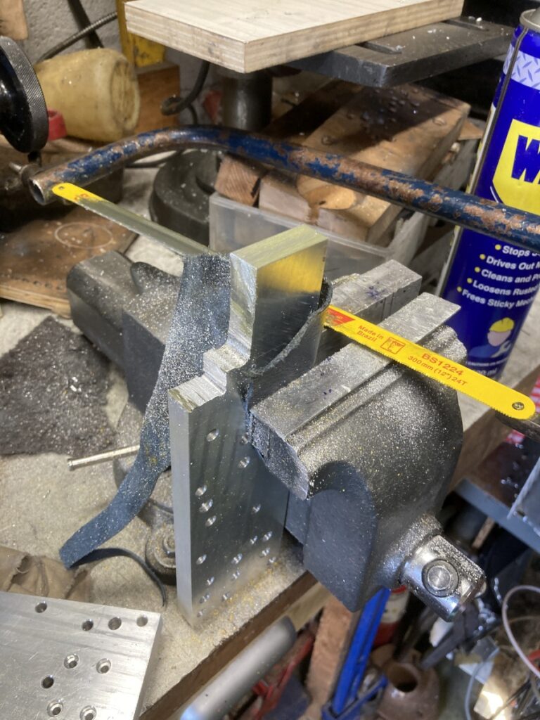
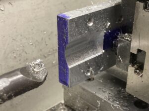
The top of each half was trimmed away with a hacksaw and cleaned up using the vertical milling slide in the lathe to allow the ballscrew nut to be mounted.
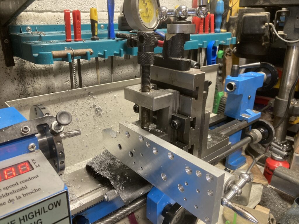
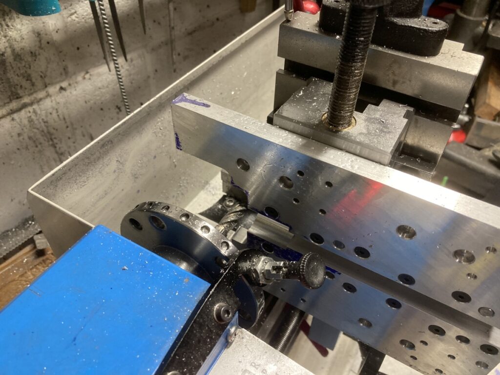
The original idea was to machine the seat for the ballscrew nut with the adaptor plate assembled, but I couldn’t fit the assembly in my lathe. Instead, each part was machined separately in a fairly precarious setup using a boring bar held off centre in the 4 jaw chuck with my fingers crossed that they matched up afterwards:
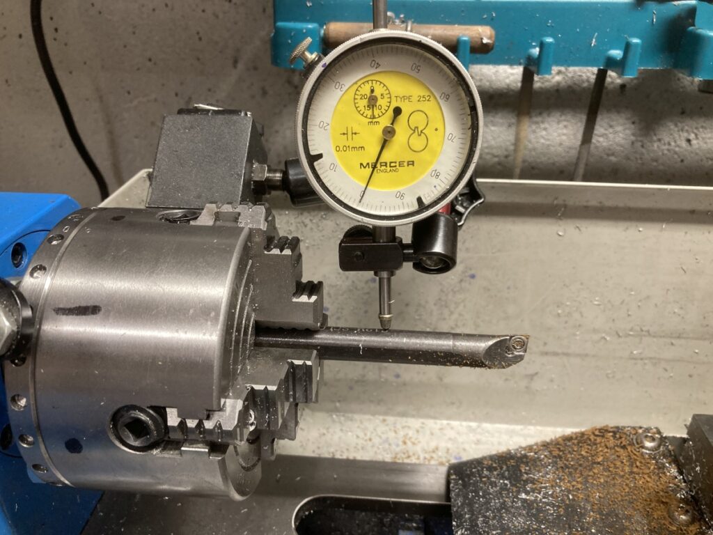
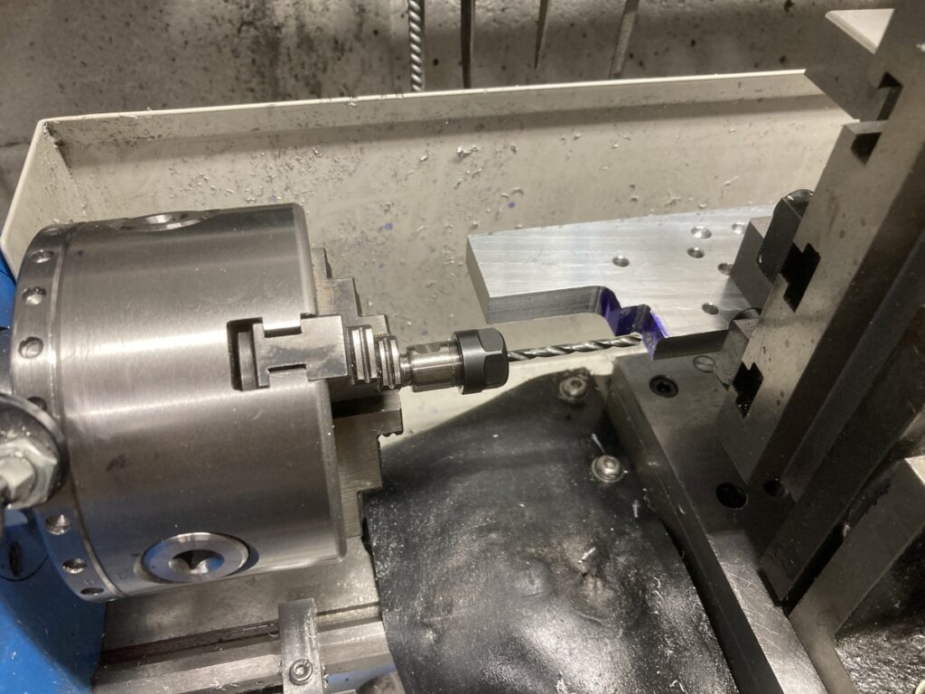
My biggest boring bar was set up in the 4 jaw chuck and offset to cut a 22mm bore – checked using a bit of wood.
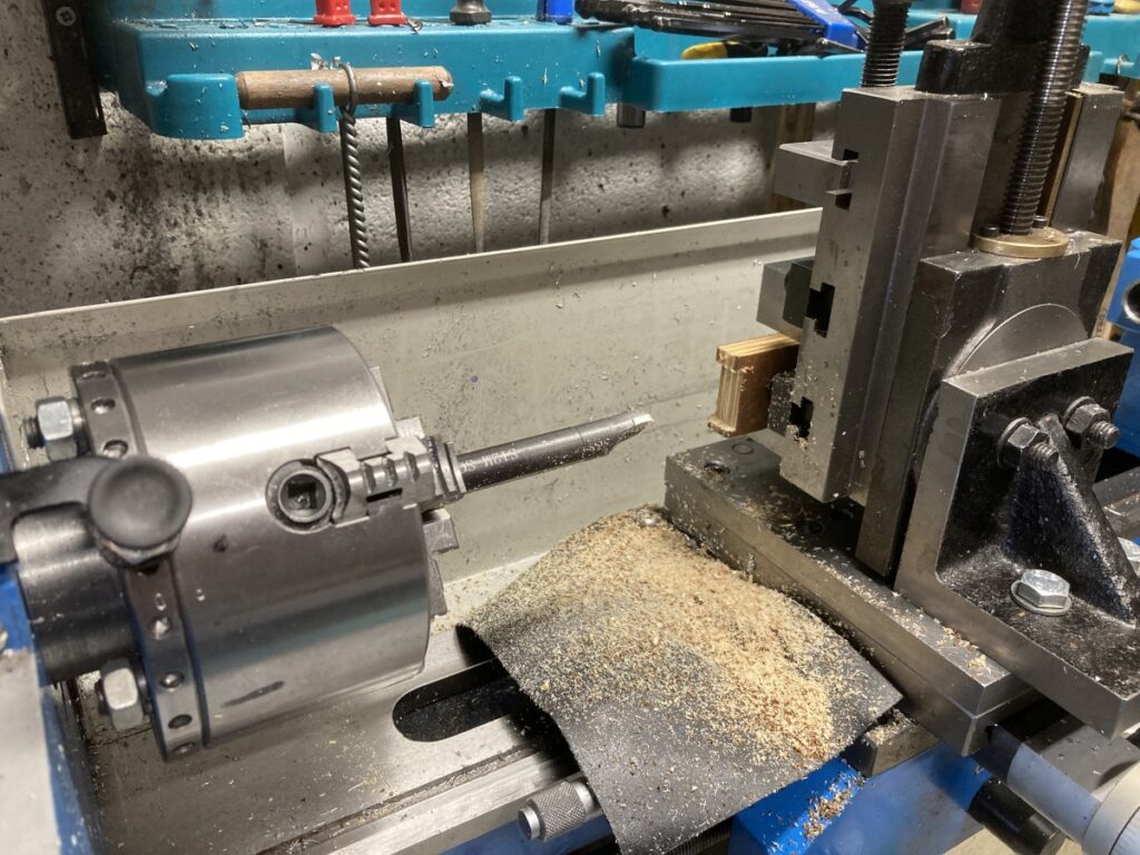
Each part was carefully lined up and bored out
Despite the extreme stick-out of the boring bar, it seemed to go OK, and I was very pleased with the way they went together.
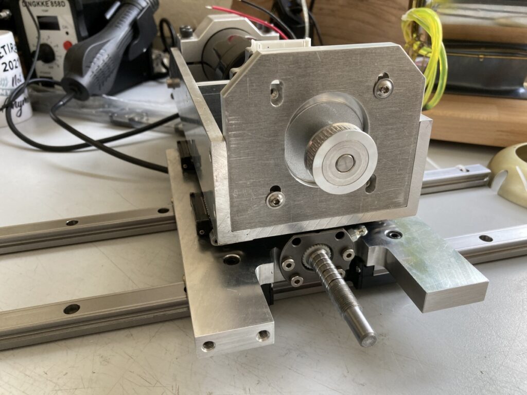
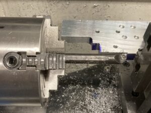
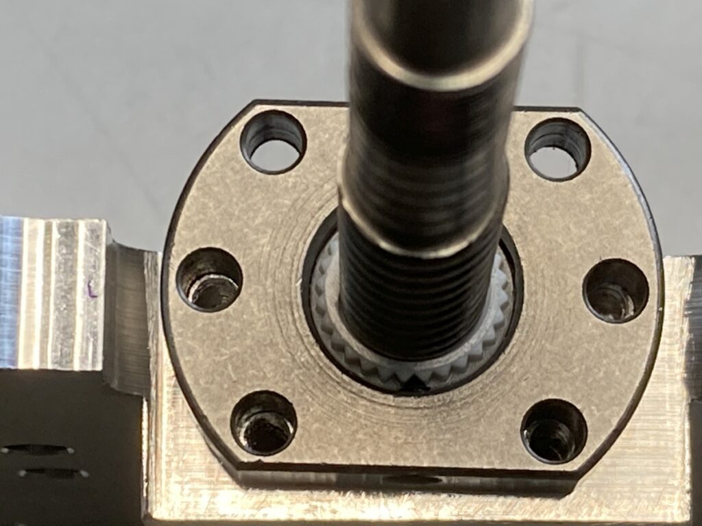
The assembled parts were then shoe-horned back onto the vertical slide to clean up the face where the ballscrew nut seats, and then to drill the holes for the ballscrew nut mounting bolts.
It came out OK in the end
When assembled to the Z axis and the X axis bearing rails, all the slides ran smoothly, and everything seemed to fit.