With my aim of keeping costs down, there was really only one option for the axis control: Open loop stepper motors.
I’d chosen the first stepper motor on the entirely unscientific basis that it came up on Aliexpress as ‘people who bought this ballscrew also bought this motor’. It was a ’23HS7628′ which turns out to be a 76mm long NEMA 23 sized motor rated at 2.9A per phase, 1.8Nm holding torque and 3.6mH inductance. When it arrived, I thought that it looked beefy enough so bought a similar one (a 57BYG stepper motor 76mm, 3.1A, 2Nm, 3.6mH which ended up on the X axis) and a slightly smaller NEMA 23, double shafted motor for the Z axis (23HS5628-SZ 2.8A,1.26Nm, 2.5 mH) – Dual shaft, because at the time, I thought I might want to add a handwheel to the Z motor – I wouldn’t bother again.
The steppers turn out to have been good choices for the machine. In conjunction with the 12mm diameter / 4mm pitch ballscrews, they give speeds of over 5000 m/min for the X and Y axes, and enough force to snap a 6mm end mill like a twig (ask me how I know!)
Since my chosen steppers could take about 3 amps per phase, I felt it put them beyond the scope of the many generic 3018 control boards that are available as the integrated drives seemed to be limited to 1.5 or 2 amps.
External drivers appeared to be available at “bargain” prices – I got 3 of these supposed TB6600 drives for about £20 all in! All is not what it seems, however.
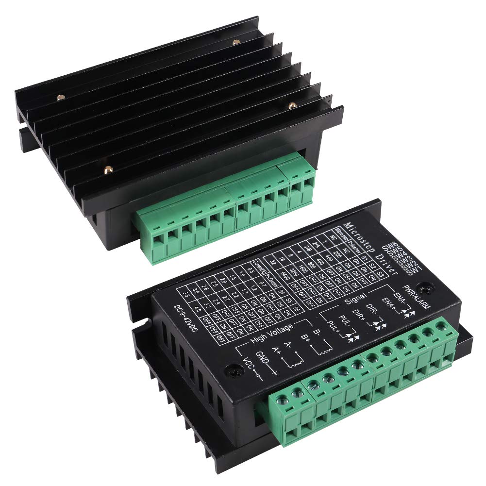
I should have done a bit more research: The real Toshiba TB6600 chip (rated at 42V / 4.5A) only goes to 16 microsteps – these drives go to 32 microsteps, and are therefore “fakes” based on some other chip – possibly the TB67S109AFTG (also a Toshiba chip, but rated at 47V / 3A). There is an interesting article here.
I only found out about this after I bought these and had been running them for a while. Touch wood, they have been performing OK at 36V and 3A.
With the drives and motors to hand, it was just too tempting to cobble things together with a spare Arduino Uno and drive the machine around…. It’s not pretty:
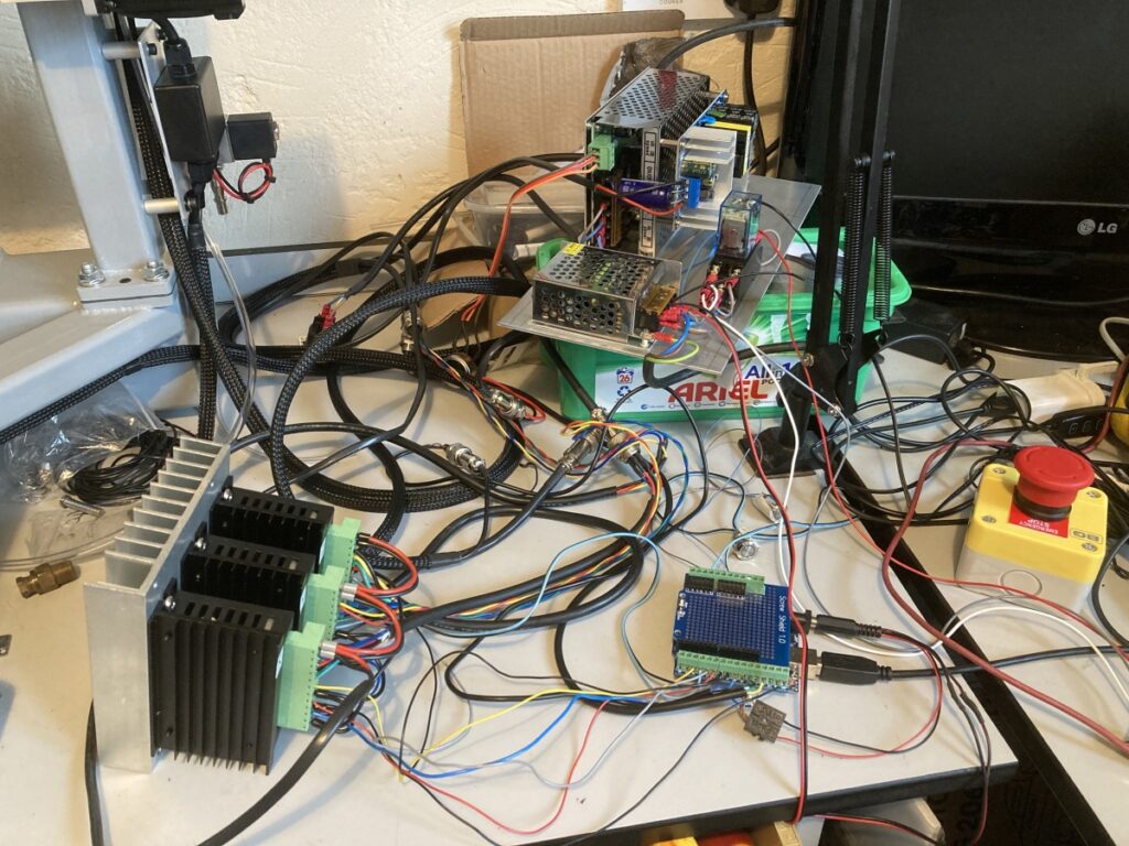
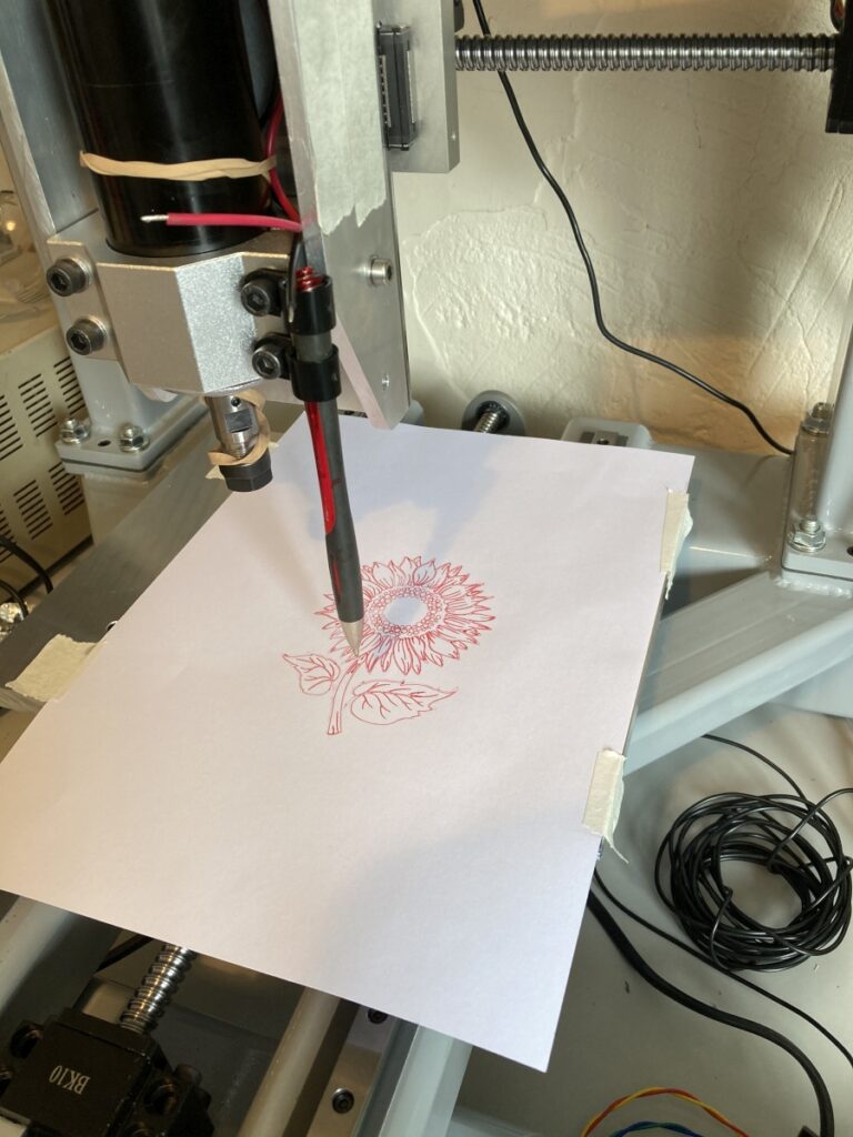
The spindle isn’t wired up, but it could draw pictures 🙂
After driving various bits off the end of their linear rails a few times (and having to play hunt the ball bearings) I resolved to fit the homing/limit switches. (I found some nice little normally closed inductive proximity switches that are only 6mm dia.)
The X axis homing/limit switch fits into the X/Z adapter and is triggered by ‘flags’ on the top of the gantry: (I was going to fit limit flags at each end of the travel, but ended up with just one that is used for homing.)
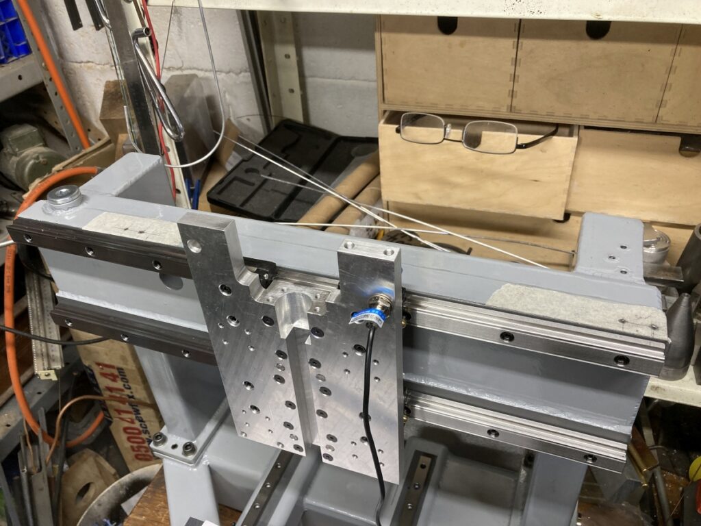
The Z axis switch fits into the hole on the other side of the X/Z adapter plate, but facing in the opposite direction to the X one. It’s triggered by ‘flags’ on the side of the Z axis.
The Y axis one is under the table:
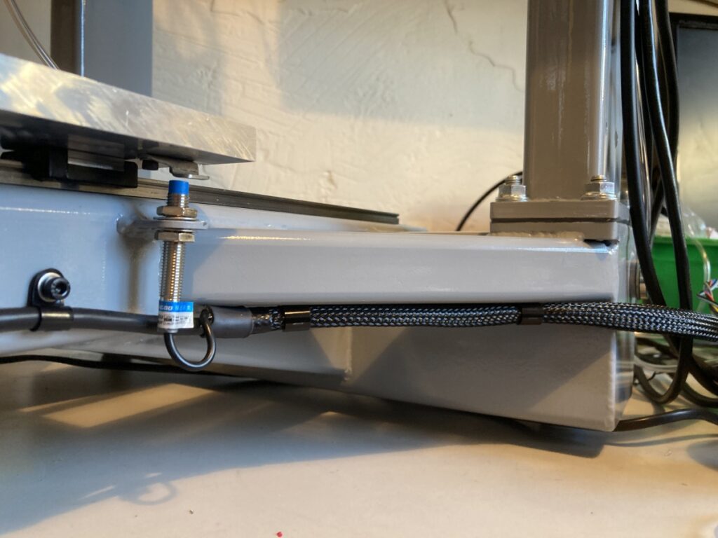
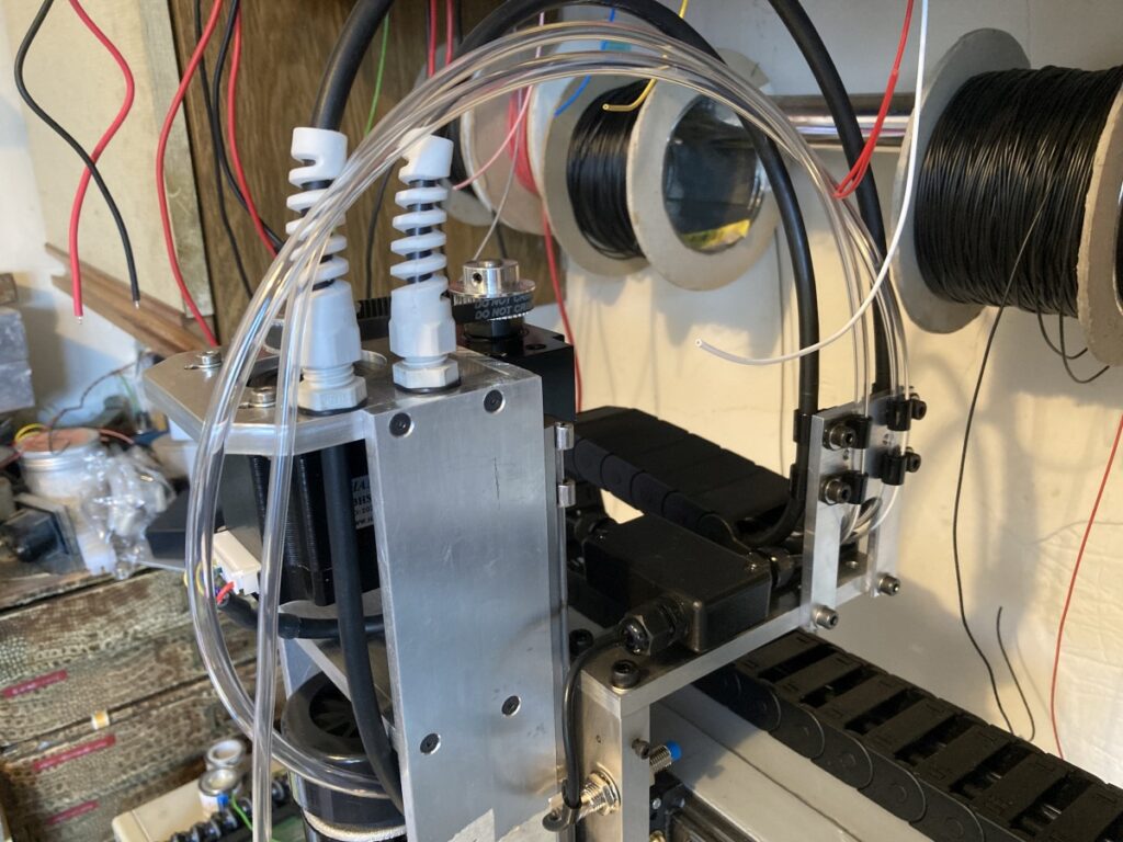
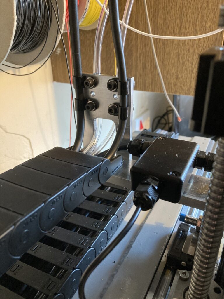
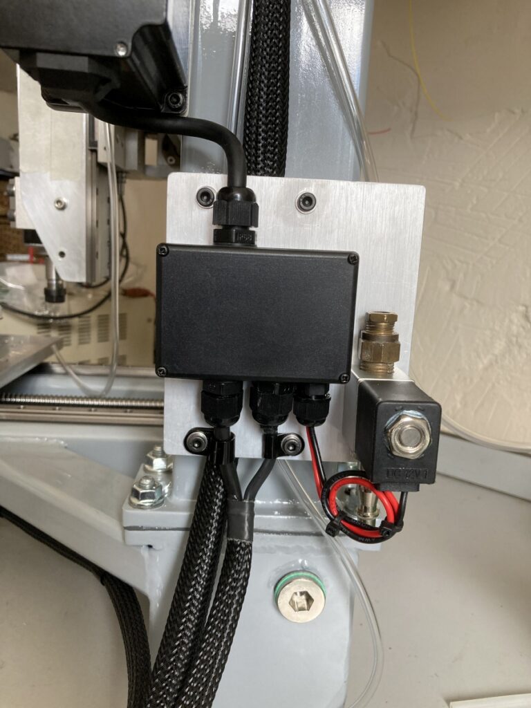
I also fitted a cable chain, etc. and did the final wiring on the machine side of things. There’s a couple of tubes there intended for an oil mist style lubricator and a solenoid for the same on the side of the machine