
Introduction
I decided to do something about the spindle – Even after the modifications above, it was still much less stiff than the structure of the machine, meaning slower feeds and light cuts to avoid chatter. This was exaggerated because the tool stick-out was more than necessary due to the depth of bore behind the collet being limited by the motor shaft.
I was a bit puzzled as to why the modified spindle wasn’t stiffer, but eventually realised that it was just a result of the ~80mm chuck overhang, the 120mm bearing spacing and a 10mm diameter shaft – it was just too bendy. I went through the whole thing on YouTube.
The New Design
After brooding on this for a while, I decided to build a new spindle assembly and use the existing one purely as a motor, driving it through a poly-vee belt.
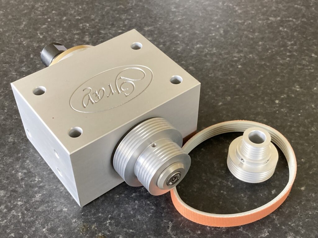
The spindle housing would be a block of aluminium that would bolt directly to the Z axis. The original spindle would get a drive pulley instead of its collet chuck and be mounted above and to one side of the new spindle. There was just enough room to fit a double pulley, giving a choice of drive ratios for a slower spindle speed (e.g. for steel).
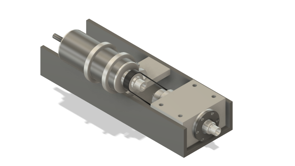
I designed the spindle around a pair of 7003 angular contact bearings (available as a preloaded, matched set as spares for spindles on Aliexpress for ~£20 delivered). It’s a pretty standard arrangement with the bearings face to face (DB configuration). The inner races are clamped together by a pair of locknuts on the shaft, and the outer races are clamped into the housing by the front cover:
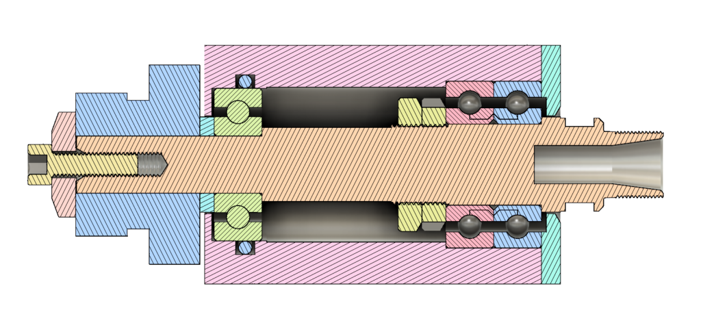
The 7003 bearings allow for a 17mm diameter shaft which should be at least 8X stiffer than the old 10mm shaft. By making the ER11 collet chuck integral with the shaft, the overhang of the collet would also be greatly reduced, further increasing stiffness. A normal, deep groove, bearing supports the tail of the spindle and takes the side load from the belt. The outer race of this bearing is a floating fit in the housing (to allow for differential expansion between the shaft and the housing), so I put an O ring around it to try and discourage it from spinning the outer race. According to SKF, for the best stiffness, the spacing between the nose and tail bearings should be 3-3.5 times the bore diameter of the nose bearings, so tht’s what I went for.
For the drive, I’m using a Megadyne TB2 poly-vee belt – these are available in the short length that would be needed (unlike J section belts).
Making the Spindle Shaft
The spindle shaft was machined from 20mm diameter EN24T (817M40T). The challenge was to get it to run as true as possible, which led to a bit of head-scratching about the best sequence of machining operations – this is what I ended up doing:
I machined the tail end first, but only roughed out the bearing journals:

I then flipped it around and centered the tail end in the 4 jaw chuck and used a fixed steady to centre drill the other end, so I could use a live centre to support it while I machined the outside of the collet chuck and cut the collet nut threads:

I used the fixed steady again to drill the collet recess and cut the internal taper

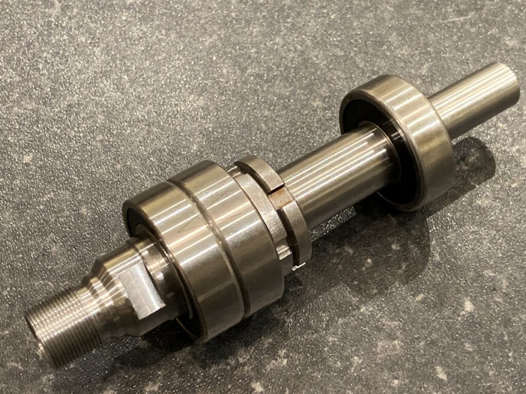
While the compound slide was set to the correct ER taper angle, I cut a small piece of brass to act as a live centre. I could then mount the spindle between centres, using the collet taper to support the ‘nose’ end of the spindle. The bearing journals were machined to 0.01mm oversize and then lapped to final size. I was very pleased that I managed to get them both pretty much spot on – just a few microns above nominal.

To finish it off, I milled some spanner flats with the vertical slide on the lathe.


I was very pleased with the way that this came out – I couldn’t detect any runout in the spindle itself, and barely any on a tool in a decent quality collet:
Assembling the Bearings
I had three attempts at fitting the A/C bearings onto the spindle. In the first two, the bearings jammed part way on – I wanted to avoid using a press. Eventually, after scrupulously cleaning everything and warming the bearings to ~60°C, they slipped into place with moderate hand pressure. The runout on the collet taper was almost undetectable until the clamping nuts were tightened, then it went up to ~3µm. After various attempts, including lapping the clamping nuts, I couldn’t improve this, but I don’t find it too hard to live with.
Making the Body
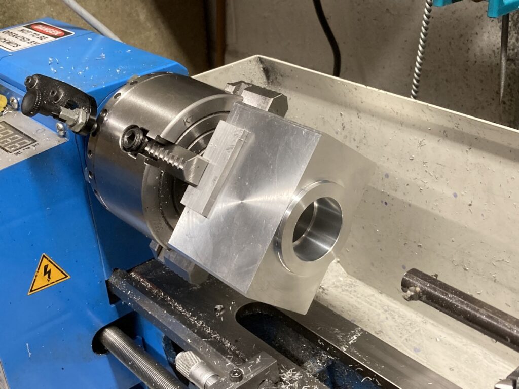
The housing was machined out of a block of 6063 aluminium that was squared up using the milling slide on the lathe (this is absolutely the biggest part that I can mill!)
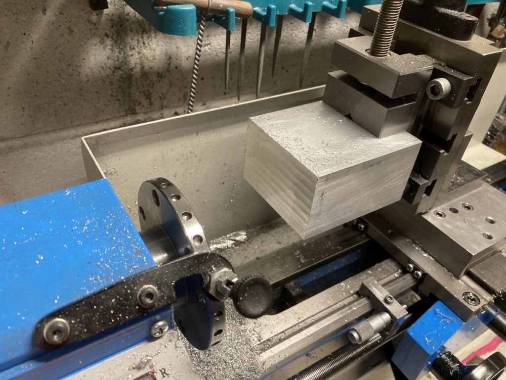
Then bored out to suit the bearing outer races.
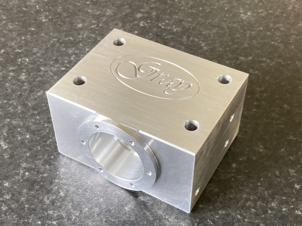
And anodised (with a bit of engraved bling)
The Drive
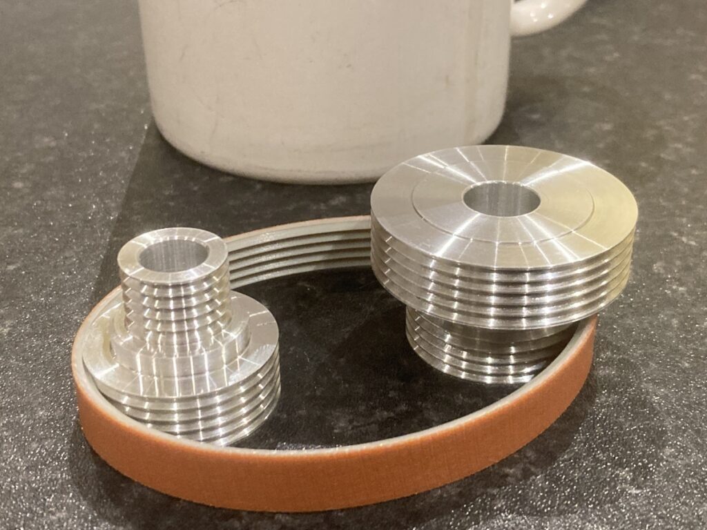
The pulleys were machined using a form tool to give the 2mm pitch / 60° grooves for the PT2 belt – the stepped pulleys give either 1:1 or 2.5:1 ratio with the same centre spacing / belt length.
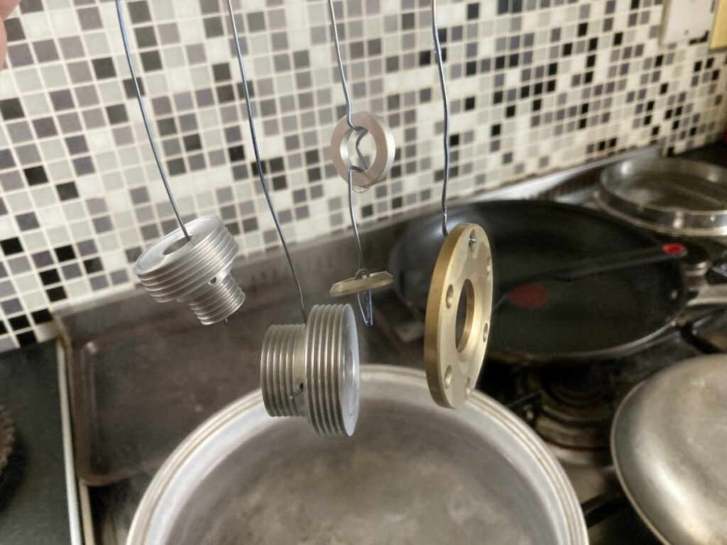
I anodised the pulleys and a few other bits together which resulted in the front clamp ring coming out an odd gold colour – I presume that this is because I’ve mixed different alloys up in the same run, but not really sure – the bath also got a bit warm which has caused some odd results previously…
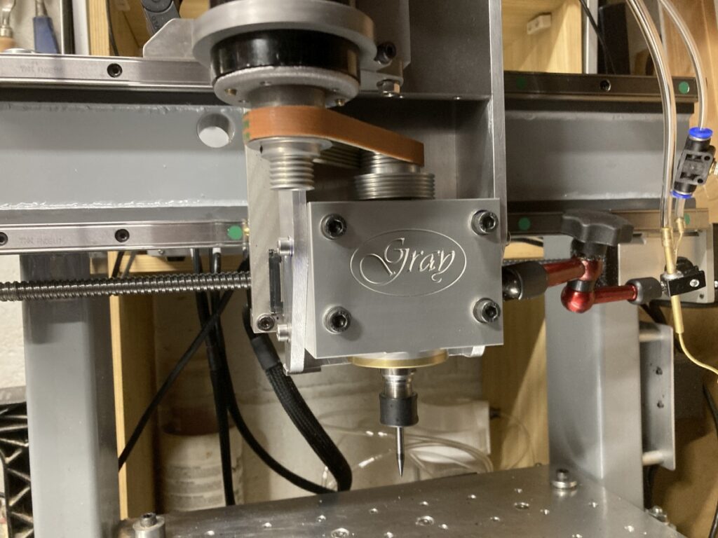
Anyway, once the bearings were on the spindle it went together very nicely:
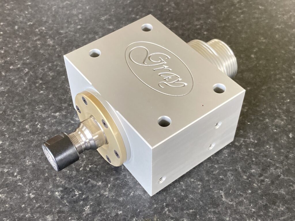
(I quite like the gold – just wish i knew how / why it had happened!)
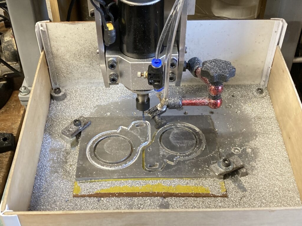
I used the existing spindle to cut a couple of clamps that would be used to mount it in its new role:
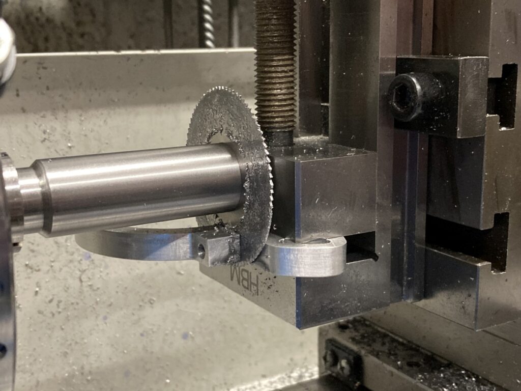
And slotted them using a slitting saw, since I already had the vertical slide on the lathe:
A bit more anodising:
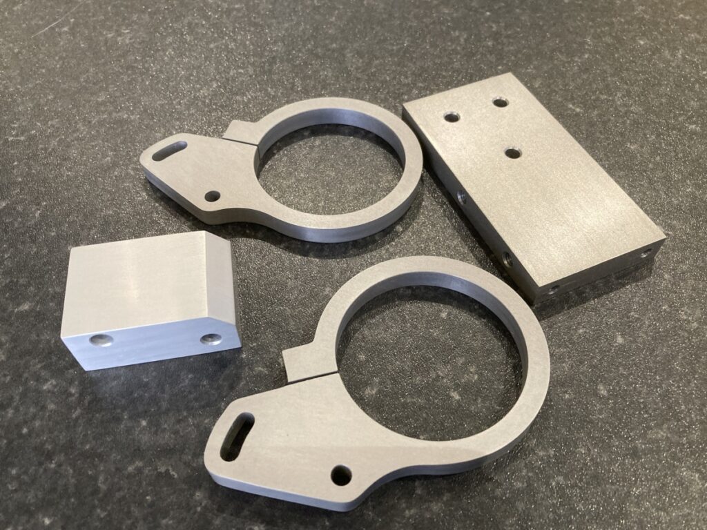
This was the second go at the mounting clamp (the first one worked out perfectly as designed, but some eejit hadn’t allowed enough clearance between the old spindle and the Z axis stepper – longer belt and new mount required!).
Getting the ER11 collet off the old spindle again turned out to be a real battle. Many bolts stripped or broken when attempting to pull it off. Heat didn’t make any difference until I turned the TIG torch onto it, when it eventually gave up.
It wasn’t pretty!
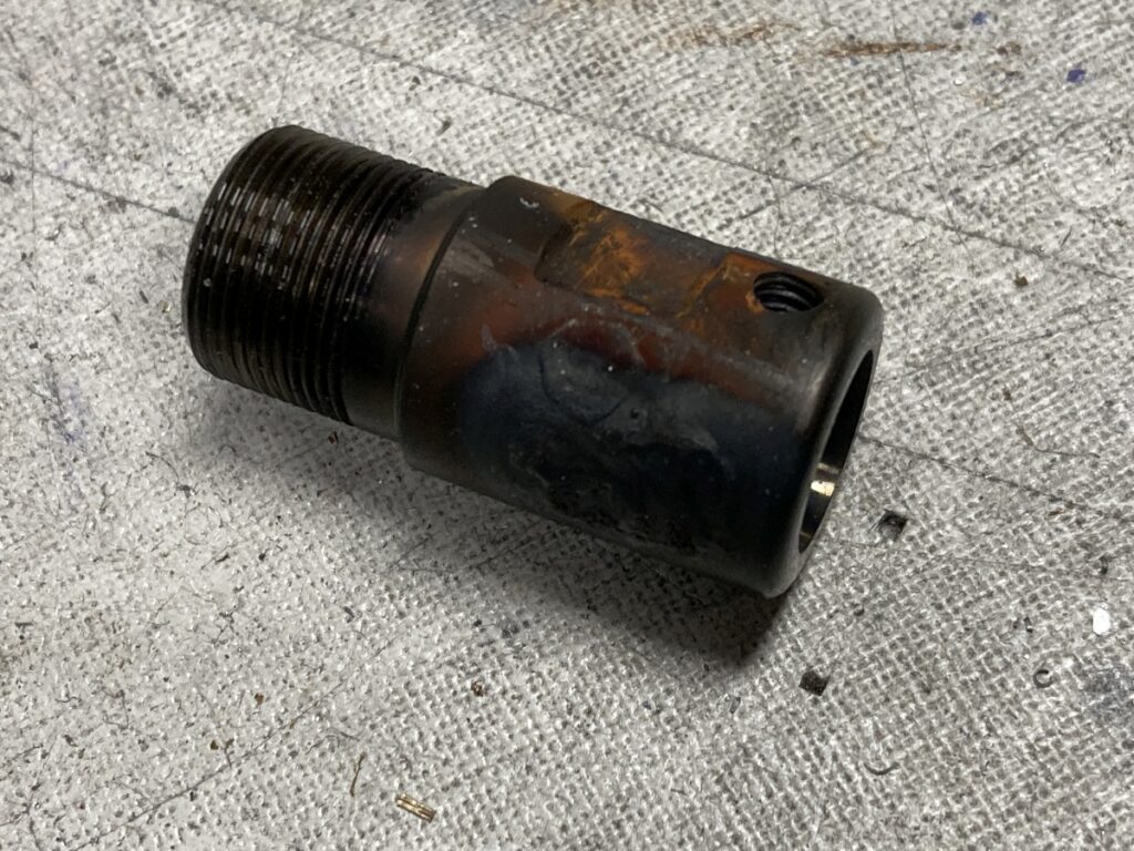
Luckily, the shaft could be cleaned up. I reversed the bearing mods that I’d previously made to the old spindle and fitted some new, standard bearings.
The End Result
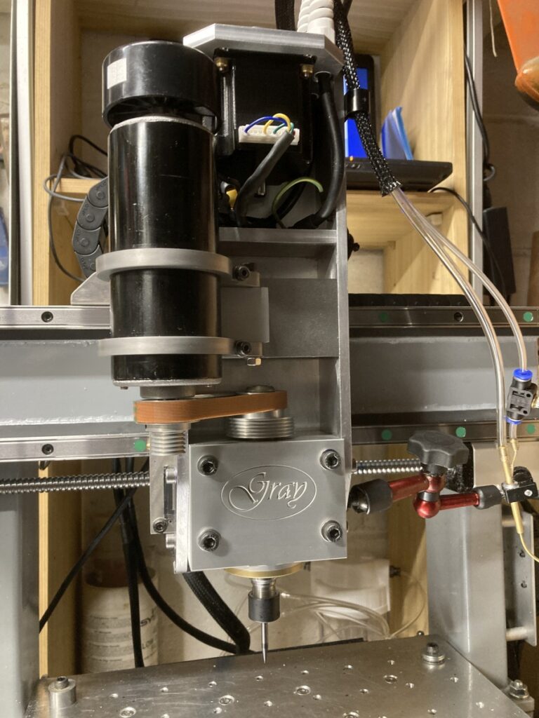
There doesn’t seem to be any measurable difference in stiffness between the spindle and the machine. The runout is also much less than the old one – I’m measuring about 4µm on the tool shank with decent collets.
From the small amount of machining that I’ve done since fitting it, it seems to be a vast improvement – it’s much quieter, too.
A very quick video of it cutting:
i just spent the last 2.5 hours reading through your build after coming across it on openbuilds after going down that rabbit hole of thinking about buying a 3018 kit on aliexpress then diving deeper like i do every year or so.
thank you for documenting the build so thoroughly. I really enjoyed reading it and couldnt put it down.
i wish i saw this before buying a cheap 500w motor off ebay 2 or 3 years ago with intent to do my own build. Unfortunatley i spent that next 8 months converting my ender 3v2 into a frankenstein lookimg ender 5 without prior knowledge of really any electrical or mechanical engineering. I probably spent more on that than if i just bought an ender 5.
Your build is giving me that itch to build one, even knowing itll be a time and money pit for me to make a jenky version. Bummed i sold the mill/lathe combo when i was unemployed last year. Anyways, thanks again for posting this. This reminds me why I need to be better at documenting my relvolving door of projects i am always tinkering with.
I never comment or post anything online, buy had to pay my respects. Hope to get to your level of skill one day! Ill try to check in on your site for any other projects you share!
Take care!
-Corbin
Thank you very much for the kind words! I’m very pleased that you found it interesting, and thank you for taking the time to comment – it is appreciated!
I enjoy making things, so the build was entertainment in itself – it’s probably cheaper to buy a machine, but where’s the fun in that 🙂
I wish you all the best with your build if you chose to go ahead – if you think I can be of help, feel free to drop me a line.
Andy