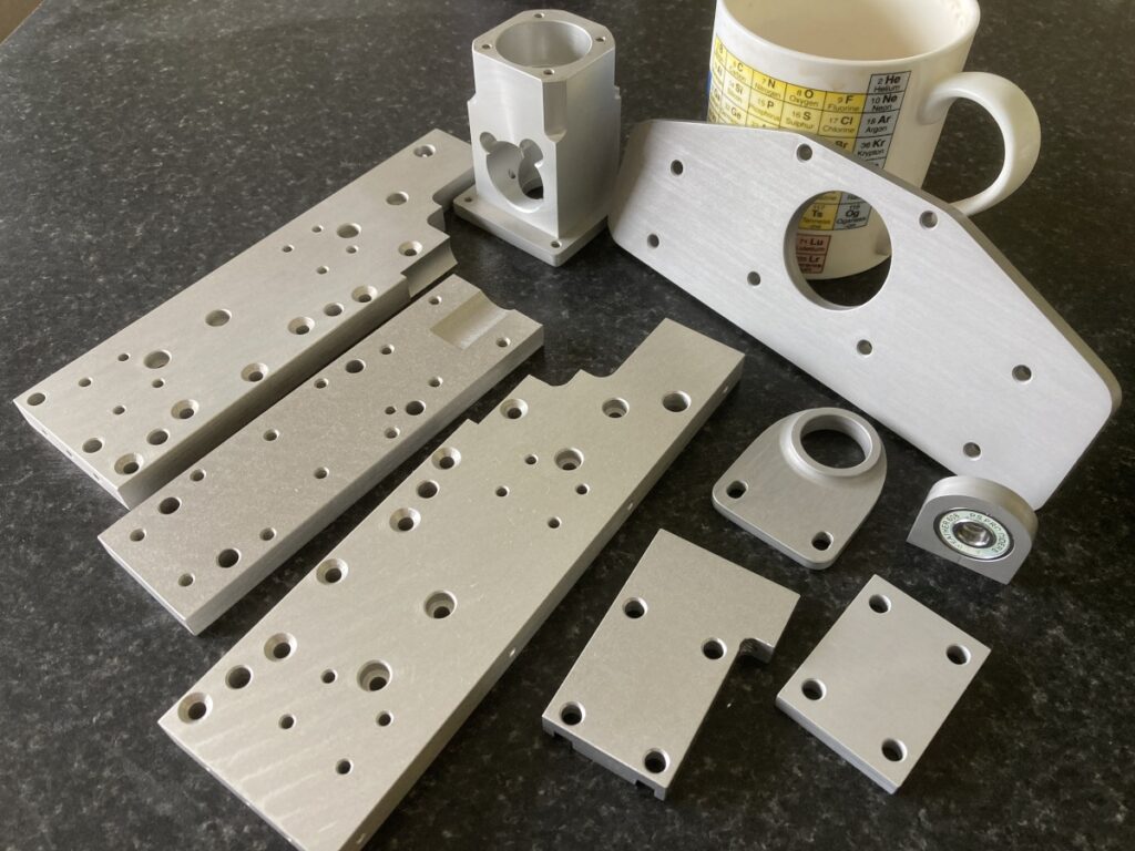
Before trying to put it all together for real, I took some of the aluminium bits apart to anodise them (details of the process I use are described here)
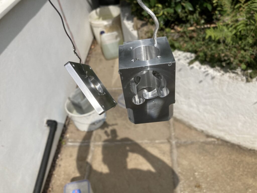
Unfortunately, after reassembling the X/Z axis plate, I ended up with a slight mismatch where the Z axis ballnut seats. I’m still not sure why – I think the fit of the dowels in the reamed holes was probably slightly looser than needed. The difference in height was only about 0.15mm, but it was enough to throw the Z axis leadscrew out of true by several mm over its length.
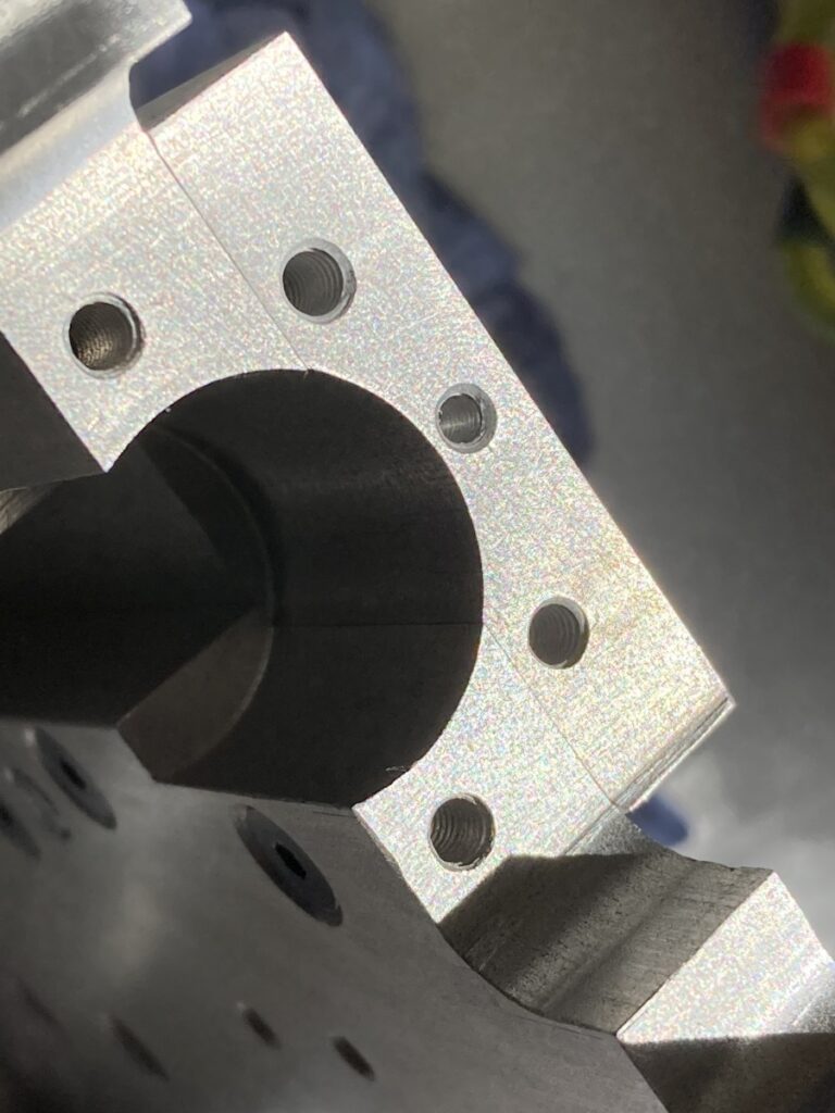
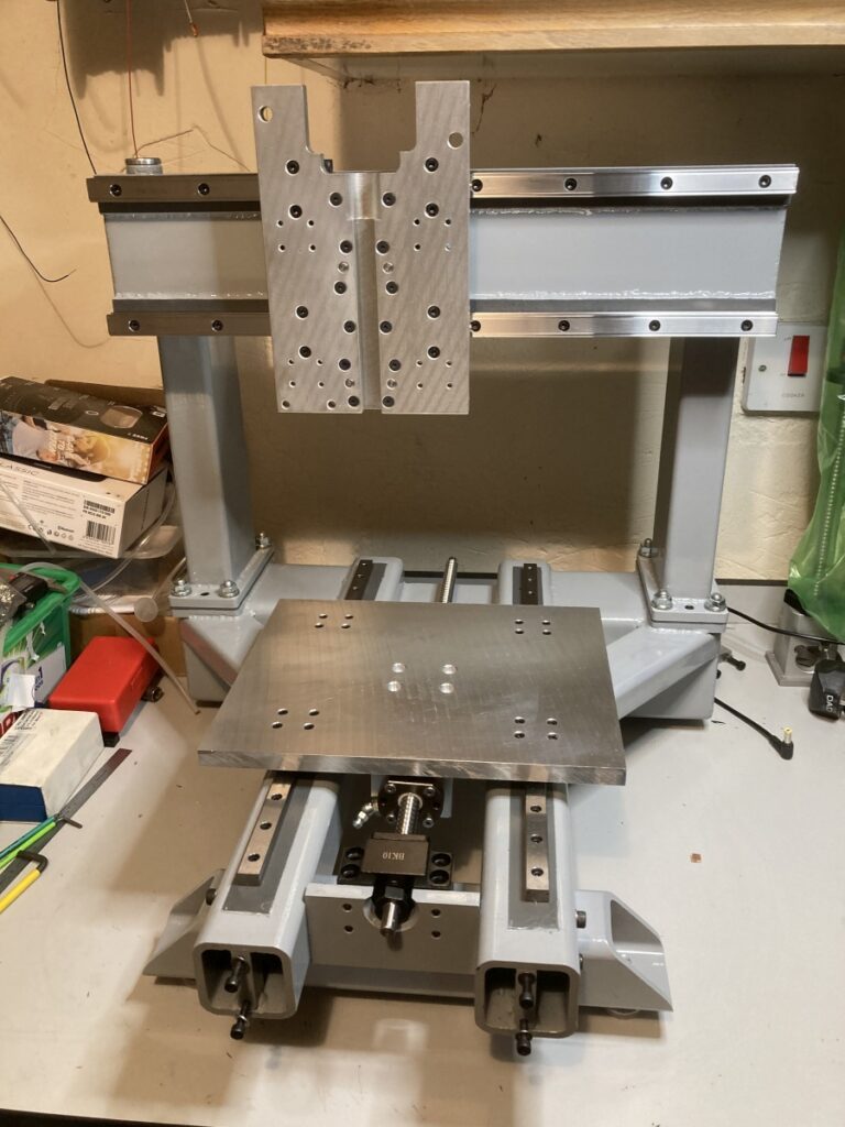
I needed to re-machine it somehow, but couldn’t fit the assembled part in my little lathe. After a lot of thought and puzzling, I came up with a cunning plan…
…Ladies and gentlemen (and the rest of you): I present the king of dodgy setups:
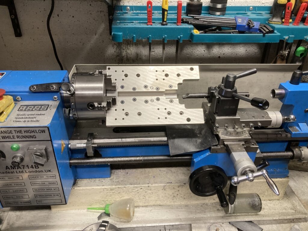
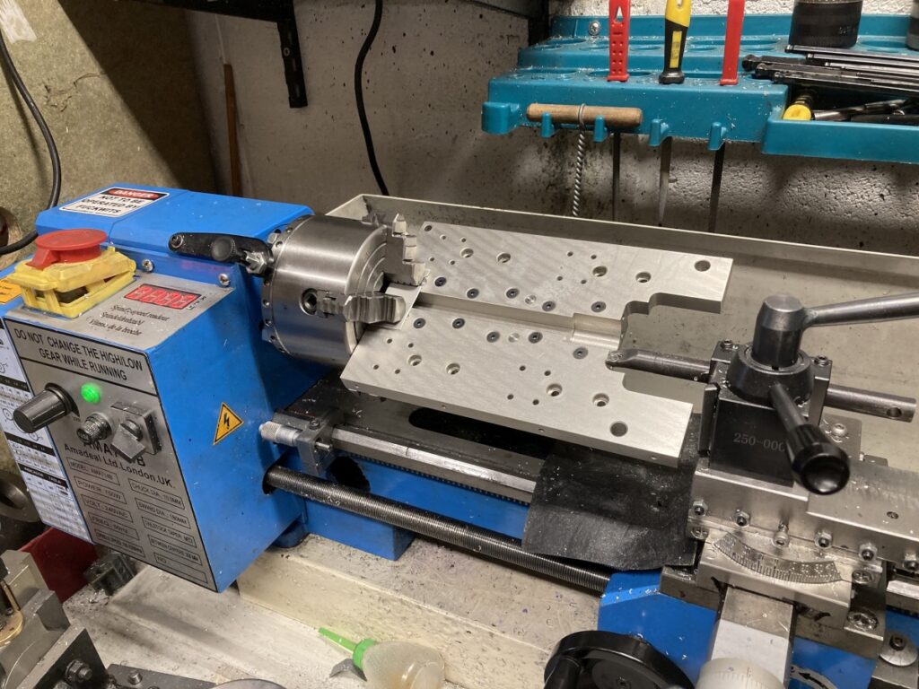
I could only hold the assembled plate between the jaws of the 4 jaw chuck (rather than inside them); The carriage needed to be backed right off to provide clearance for it all to spin and the boring bar had to be stuck out a long way to reach down to the the offending area.
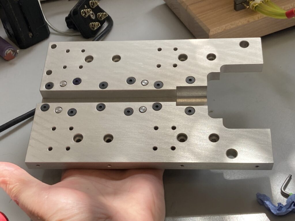
With fingers firmly crossed, I took very light cuts with the boring bar to clean up the ballscrew face. I can’t pretend that I wasn’t nervous, but it worked a treat!
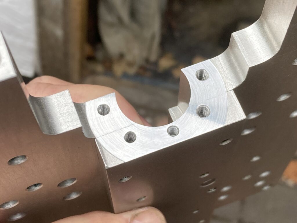
All I had to do was assemble it now.
I haven’t really got the means to machine the mounting faces of the gantry feet properly flat, so Instead, I intended to use epoxy as a shimming material. (There’s a good video about the technique from Stefan Gotteswinter on Youtube here ). This process meant that I would need to get the gantry and base accurately aligned in all 3 axes before the epoxy set.
I fitted studs to the holes in the base and to try and stop the epoxy squeezing up the bolt holes in the gantry, I put an O ring around each stud.
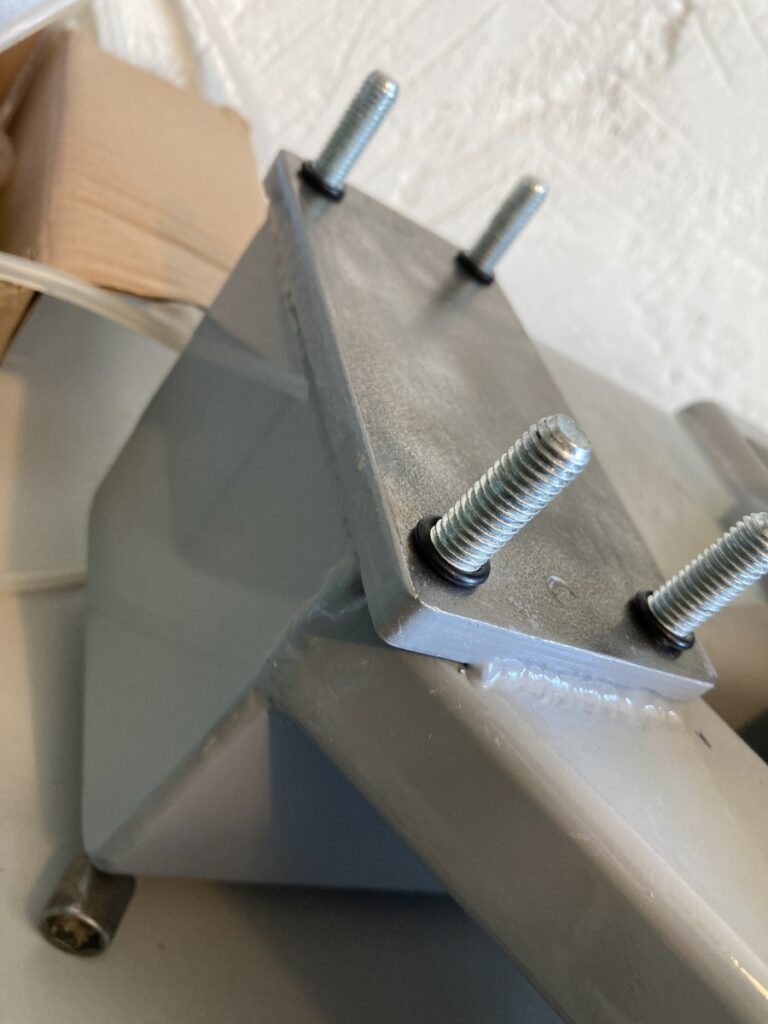
The process normally requires adding a few slugs of soft metal (annealed copper or aluminium) between the mating faces to give something for the faces to clamp against whilst they are being adjusted, but I figured that the O-rings would also fulfill that purpose. (To anyone reading this that is contemplating doing the same thing: Use the metal slugs!)
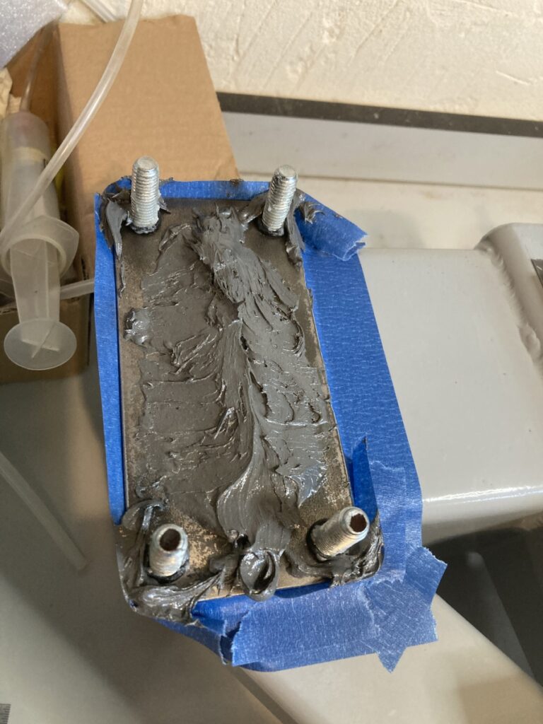
The studs themselves and metal faces were also given a coating of furniture wax to act as a release agent. After a dry run with bits of packing, etc. to make sure it was possible to get it all set square, I masked off the area around the joints and gave the mounting faces a liberal buttering of epoxy:
Do you ever wish you hadn’t started something at 10:00 at night? There followed a frantic and stressful couple of hours trying to get the gantry level to the table (side to side), and square to the Y rail travel and standing vertical (nod), all at the same time.
I’d bought myself a 6″ square to act as a reference, but I only had the one, so had to check each direction separately (with the square lightly clamped in place), make an adjustment, then go back and find out if it had affected any of the others (usually it had!).
I’d put jacking screws at the front and back of the flanges on the gantry feet to help with this process, and while they worked fine for levelling the gantry and correcting for nod, I’d completely overlooked the need to adjust the angle of the gantry to square the X and Y axes. The O rings I’d fitted on the studs were quite effective in keeping the studs centred in their holes – not where I wanted them to be! After a lot of sweat, frustration (and almost tears), I got the gantry and table reasonably squared (I ended up hammering a screwdriver down one of the stud holes to stop the blimmin’ thing creeping back on me).
I could check whether the gantry was level to the table (side to side) using a dial gauge mounted on the X carriage and running it against the table. I got it level to within ~0.03mm over ~200mm as far as I could tell with the slightly warped table. (I intended to machine the table in-situ to level it off later).
To check the perpendicularity of the axes, the square was lightly clamped to the X axis rails with a dial indicator on the Y axis. This came out to slightly better than ~0.01mm over ~100mm.
I was checking for ‘nod’ by lightly clamping the square to the face of the X axis rails and running the dial indicator on the underside along the Y axis. I eventually got it to ~0.01mm over ~100mm
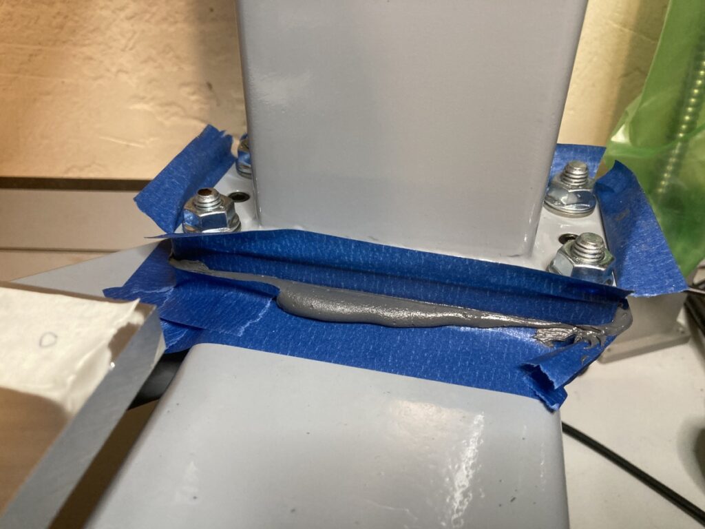
There was a healthy amount of squeeze-out from the joints that also had to be cleaned up before I could get to bed.
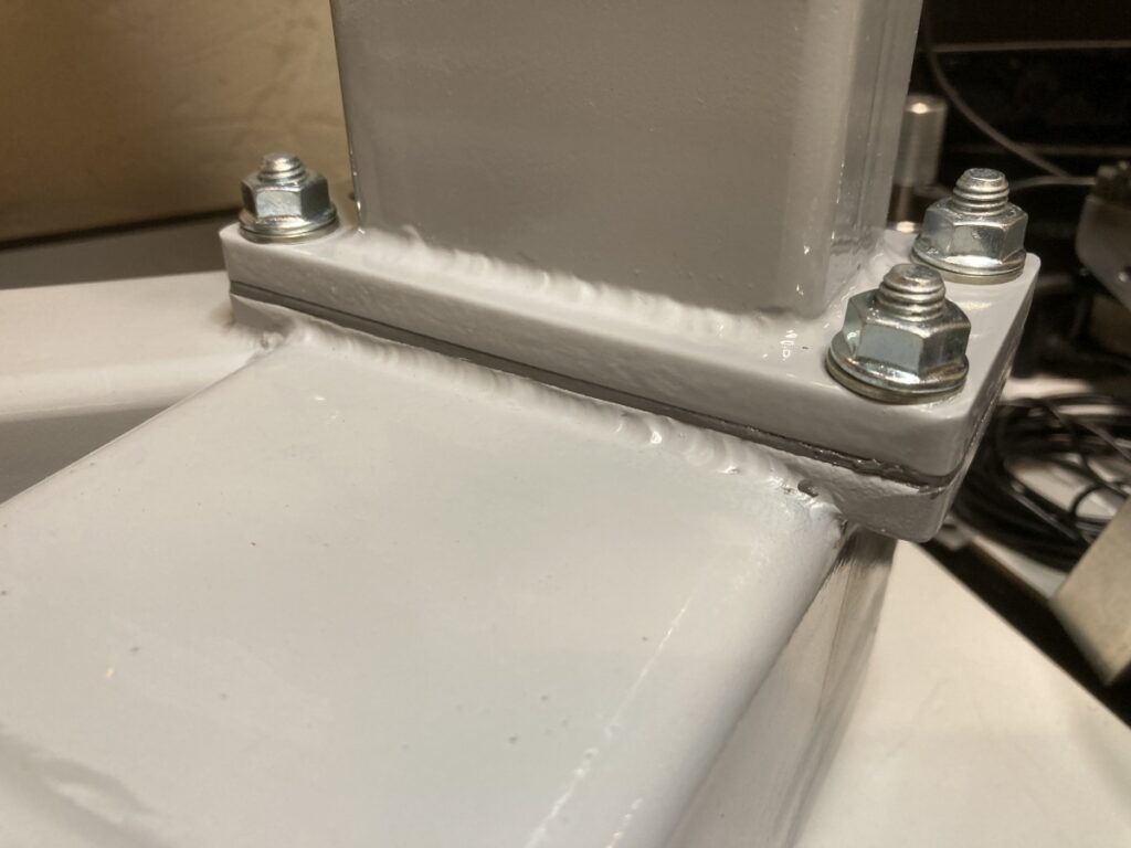
After a couple of days for the epoxy to go off, I fully tightened the nuts on the mounting studs and re-checked the perpendiculatity, etc. Thakfully it was all pretty much unchanged.