
I spent some time looking for a cheap surface plate to use as the machine base, but couldn’t find anything that was cheap enough and not 200 miles away. So I went on the scrounge to see what steel I could find. I came back with some 80 x 80 x 3 mm box (again thinner than I would have liked) and some 50 x 50 x 5 mm which would do just fine for the Y axis.
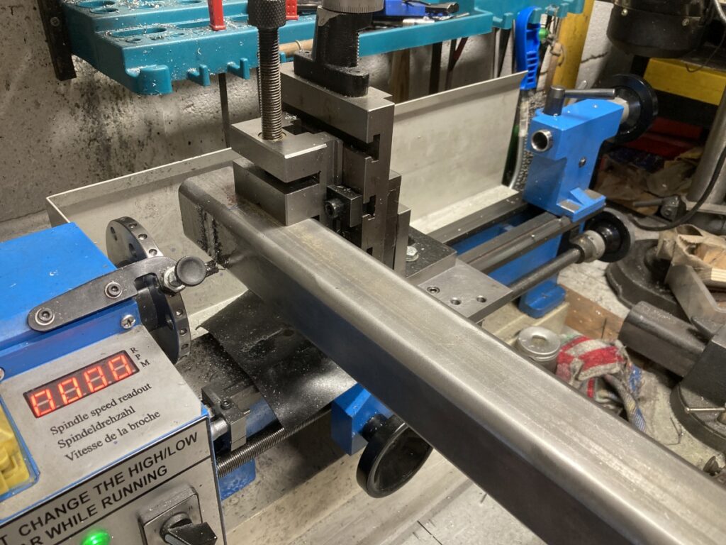
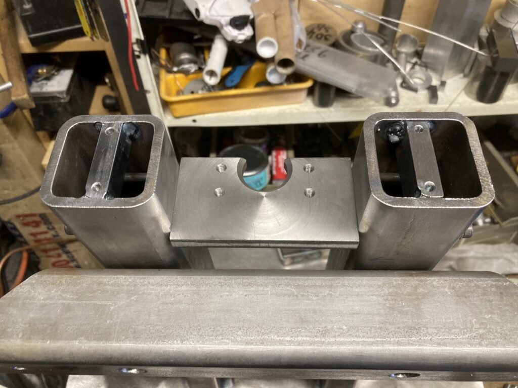
I cut a couple of lengths of the 50 x 50 and squared them up the best I could with files then wrestled them into the vertical slide on the lathe to clean up a slot for the leadscrew bearing mount:
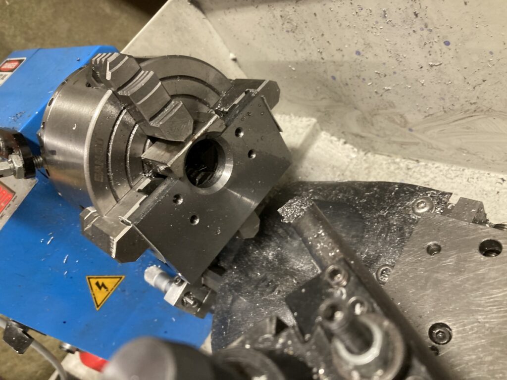
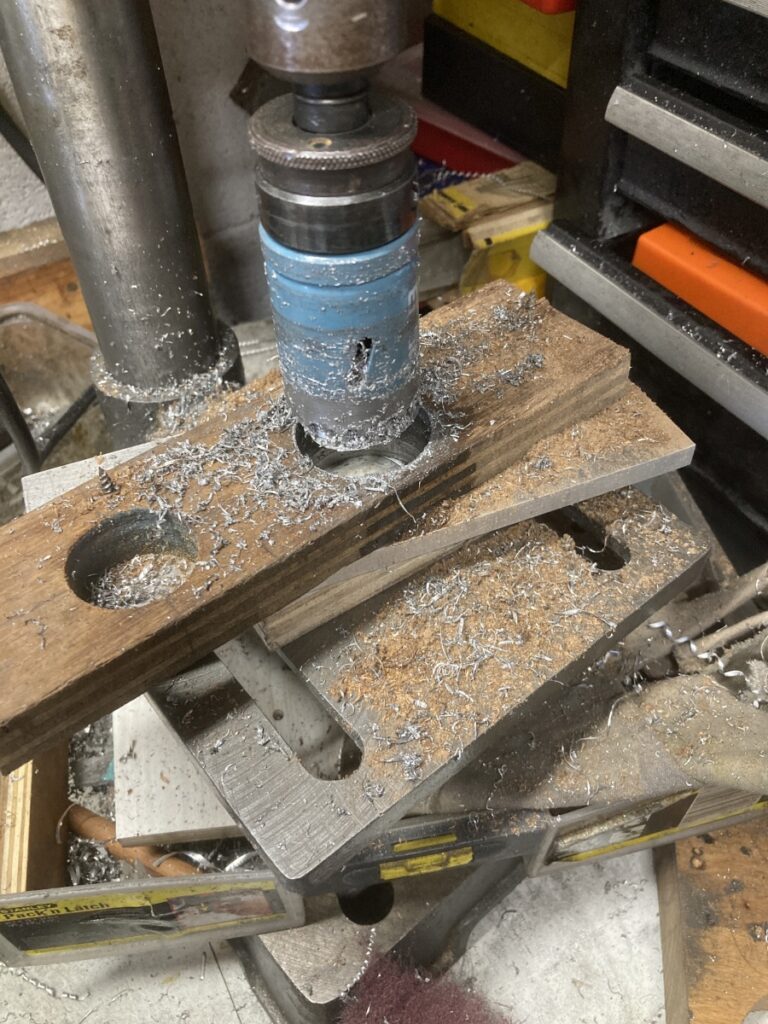
The bearing mount itself needed 3/4 of a hole boring in it
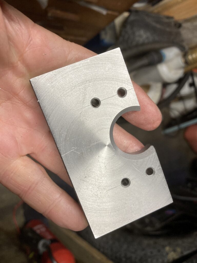
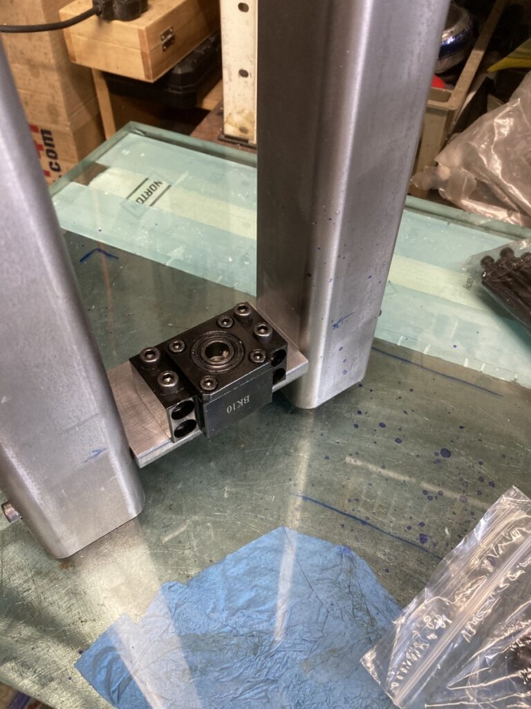
The bracket is bolted to through the 50 x 50 so that it’s angle can be tweaked to be truly square to the Y axis leadscrew. The thrust bearing is a standard BK10 part from China. (I changed the standard ball bearings it came with for some angular contact ones.)
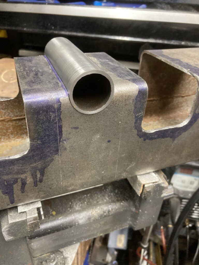
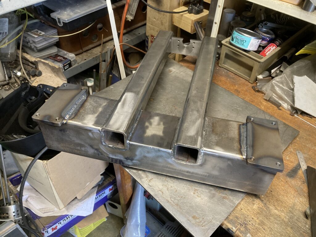
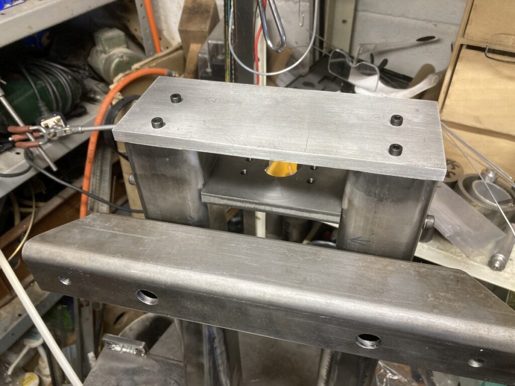
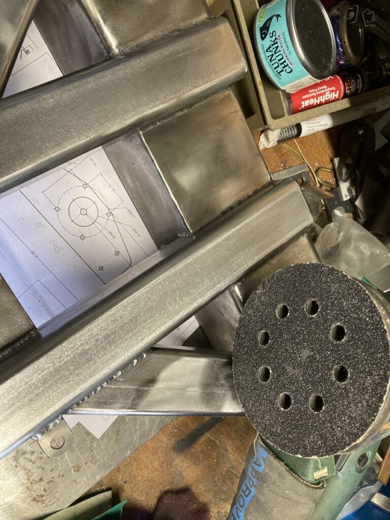
With the 50 x 50 spacing set, I cut out the 80 x 80 section to suit. I spent some time getting a neat, circular channel to take the leadscrew

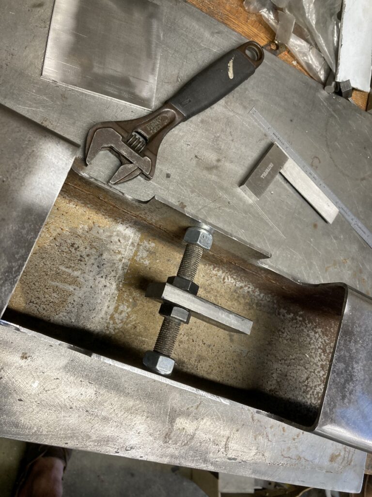
But then realised that it would make assembly very difficult (and potentially limit the Y travel) if the Y ball nut couldn’t clear the 80 x 80, so I ended up reducing the height of the whole area between the 50 x 50 sections.
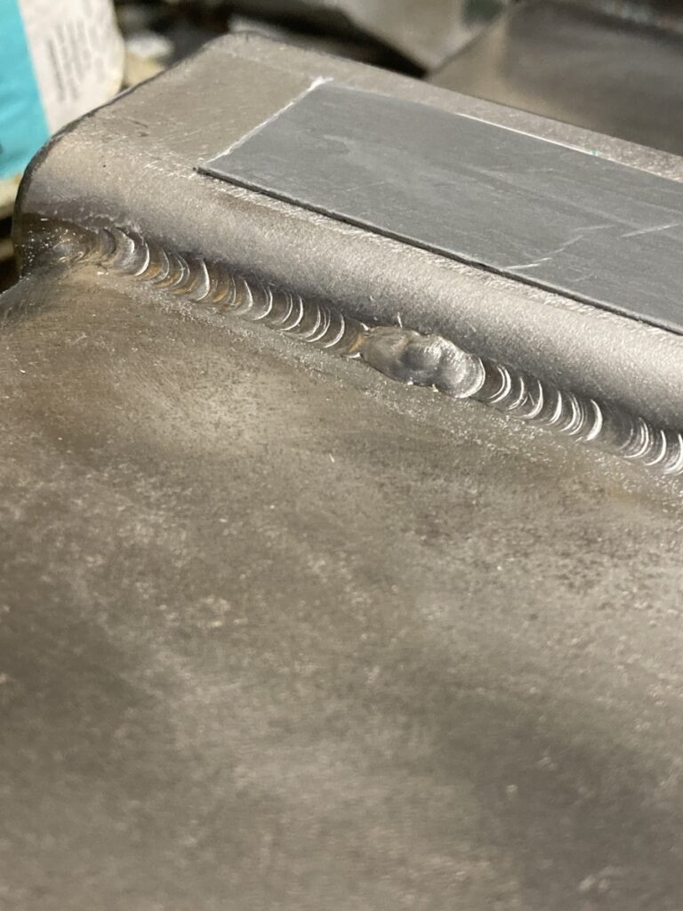
When I cut the top of the 80 x 80 away, the edges sprang inwards, so I had to jack them out again with a stack of nuts and bolts while I welded it up.
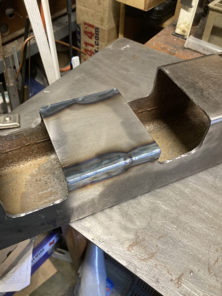
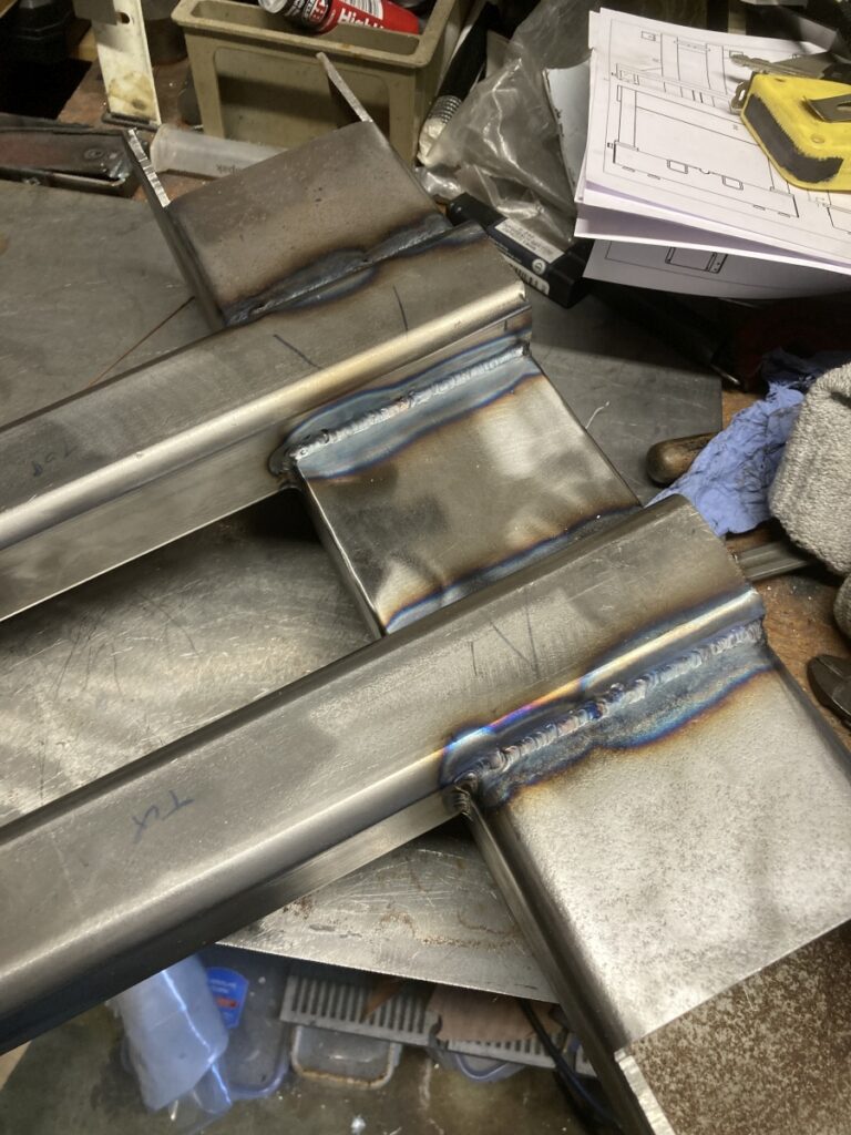
I added some gussets to try and brace the 50 x 50 rails to the bottom corner of the 80 x 80
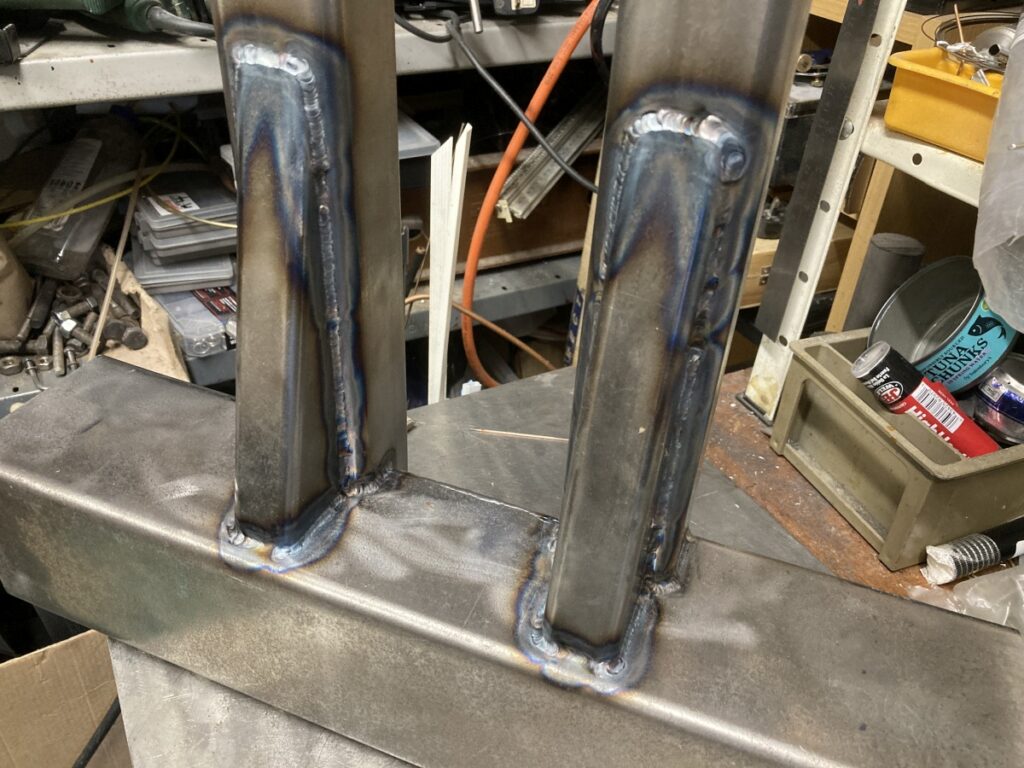
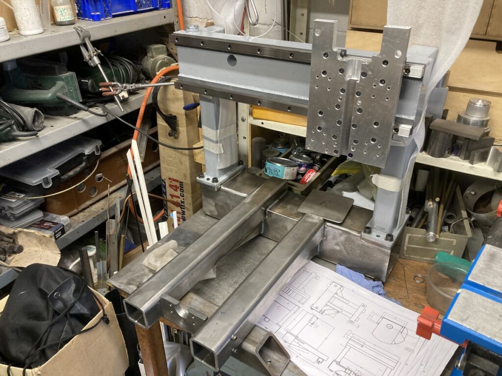
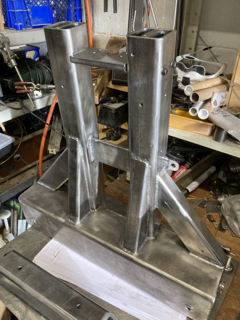
Before welding the mounting flanges for the gantry feet I put the gantry in position and set it level to the base and squared it up as well as I could.
Everything will be squared up properly when the thing is finally assembled, and the flanges bedded in epoxy, but I wanted to get it as close as I could at this stage.
Gantry flanges welded on:
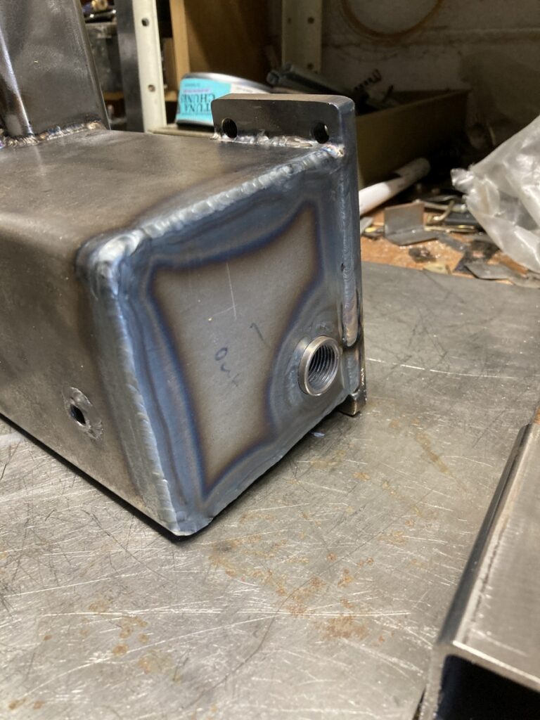
Ends of the 80 x 80 capped off (with a bung for adding filling if necessary)
Cross bar bolted on to mount some front feet.
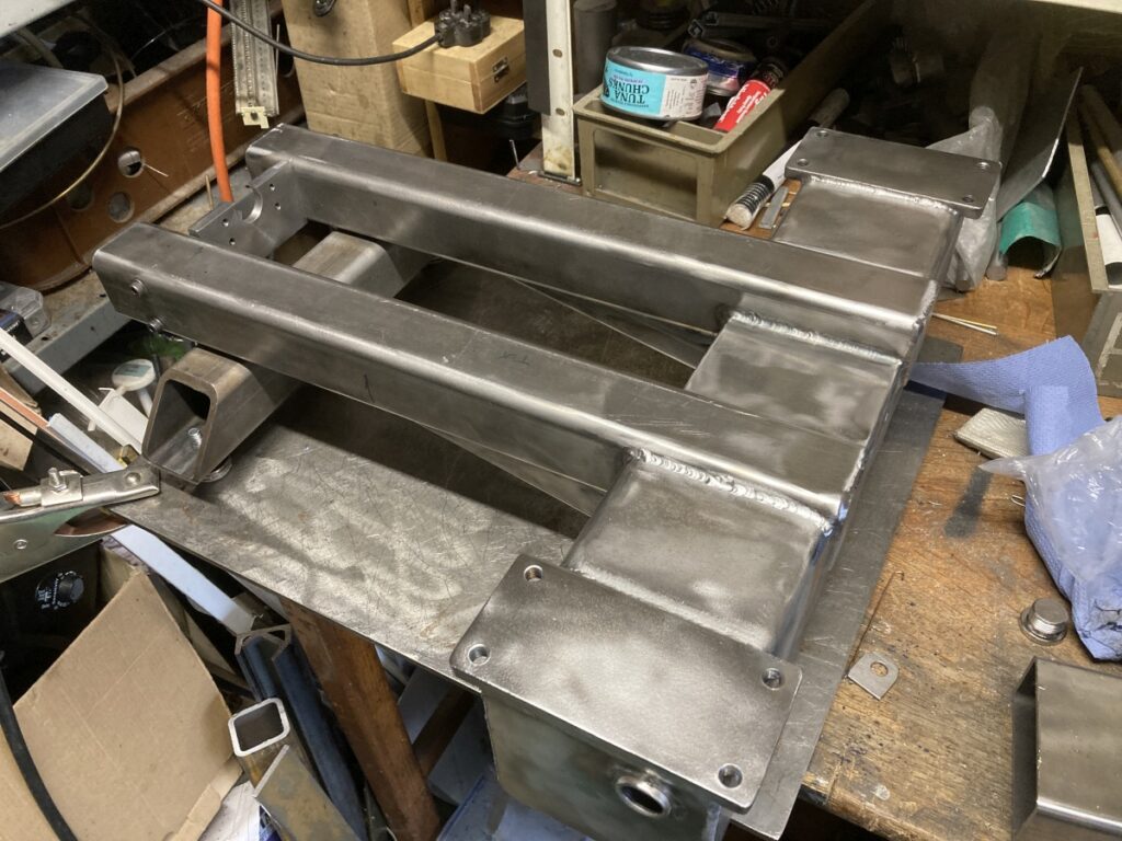
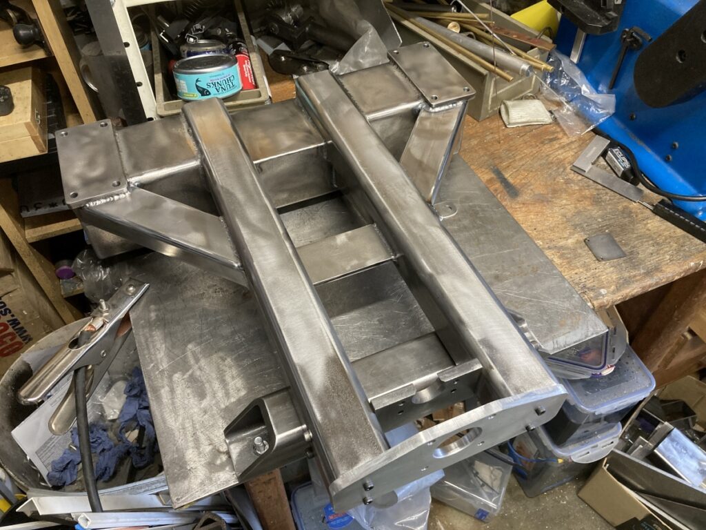
This was the state of play at this stage:
The mount for the Y axis stepper is bolted to the ends of the two 50 x 50 sections (I couldn’t think of a better way of doing it).
I welded a couple of blocks into the ends of the sections to give something to fix the stepper mount to
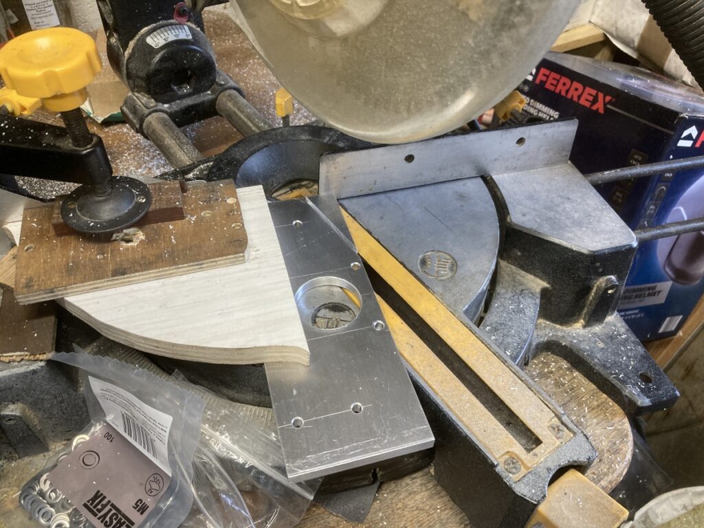
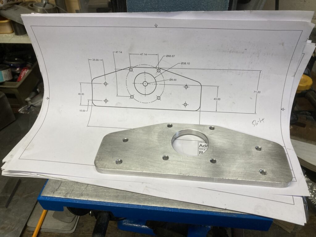
And hacked a mount out of aluminium (wouldn’t it be nice to have a CNC to do this stuff?
I thought that the Y axis still looked a bit flimsy in the side-to-side direction so welded in a bit more bracing – trying to tie the Y rails into the gantry feet
I capped all the open ends and welded in a few more blind bushes where I expected to need to fix something
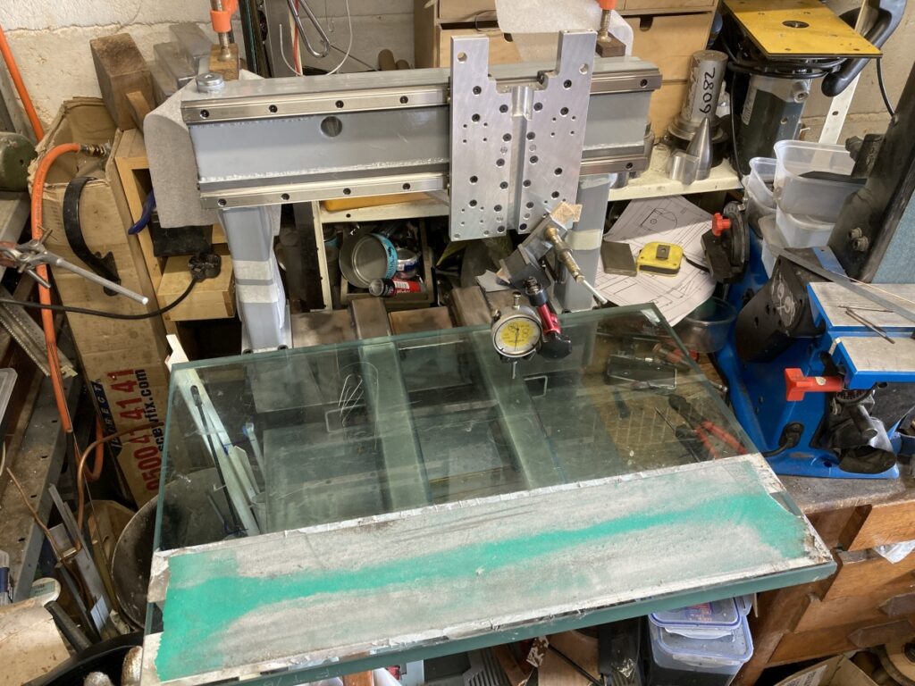
I then keyed up the tops of the rails with some coarse paper on the sander before masking them up and doing the epoxy thing again to try and level them off
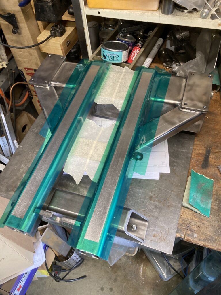
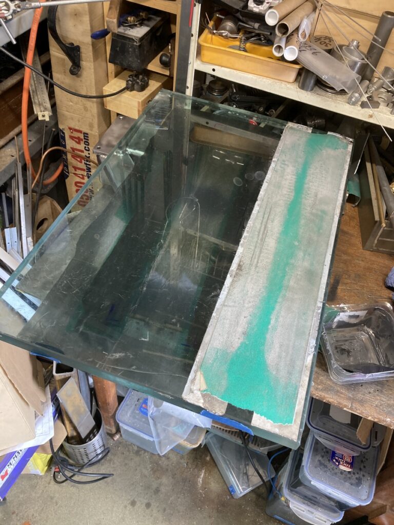
Again, it seemed to work OK.
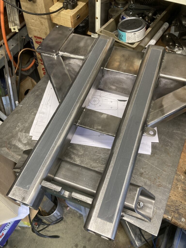
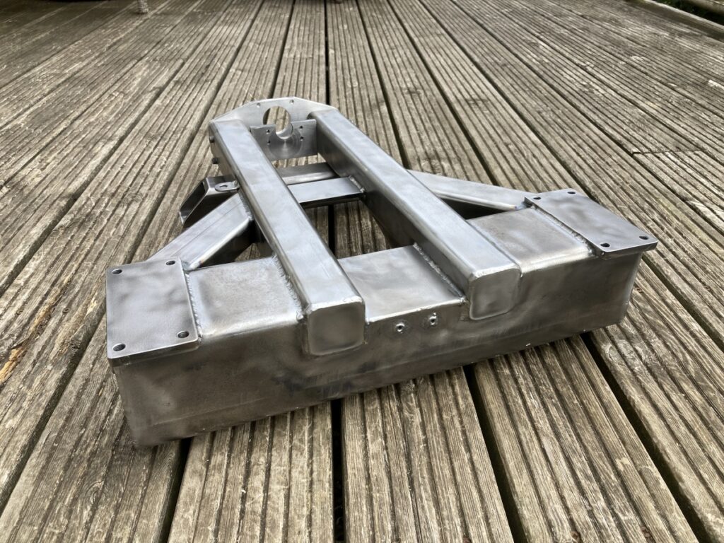
A slightly better paint job
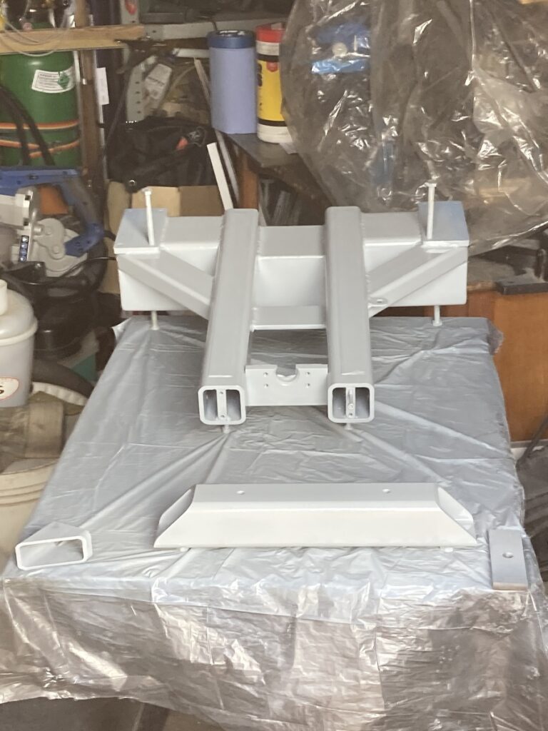
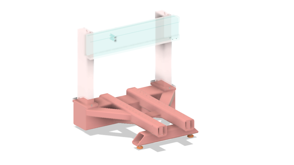
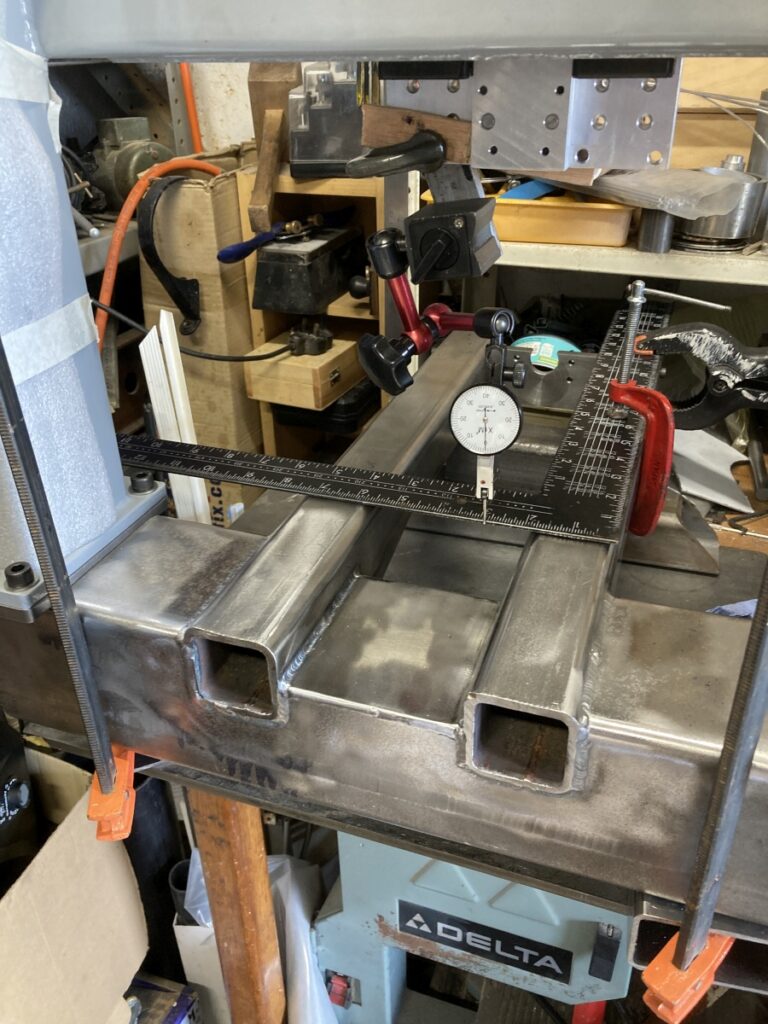
And a look at progress so far.
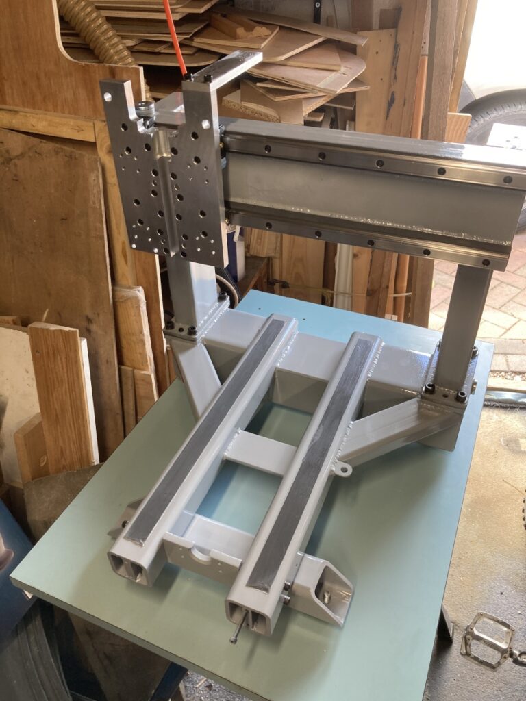
The little tab on the side of one of the 50 x 50 sections is to hold the Y axis home/ limit switch – the X and Z axis switches fit into the larger holes each side of the X carriage plate.