
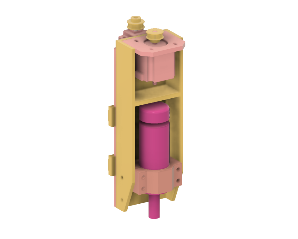
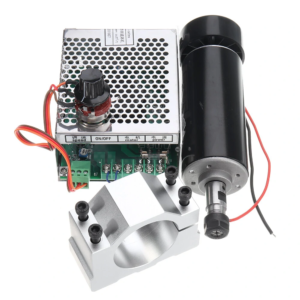
I started with the spindle and built the Z axis to suit it – The splindle was one of the cheap, 500W ER11 DC spindle motors that’s all over ebay, amazon, etc. At the time I didn’t know better, but DO NOT do the same (I will explain why in due course).
The main body of the Z axis was made from a length of aluminium ‘U’ section extrusion (100 x 50 x 6mm) with a few stiffeners bolted across it. I thought it would be stiffer and lighter than the thick, flat plate that people often seem to use.
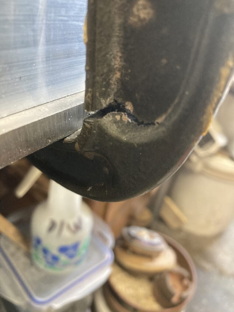
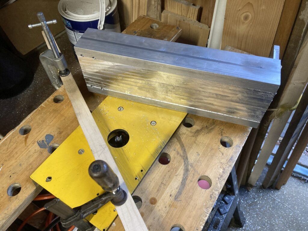
I wanted to mount the linear rails on the back of the U section, but (as expected) it wasn’t flat:
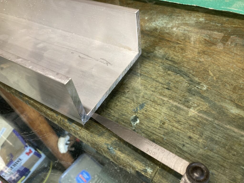
(The extrusion is resting on a piece of 1″ thick plate glass which is the nearest thing I’ve got to a surface table)
The first thing I tried was to bend the section back square…
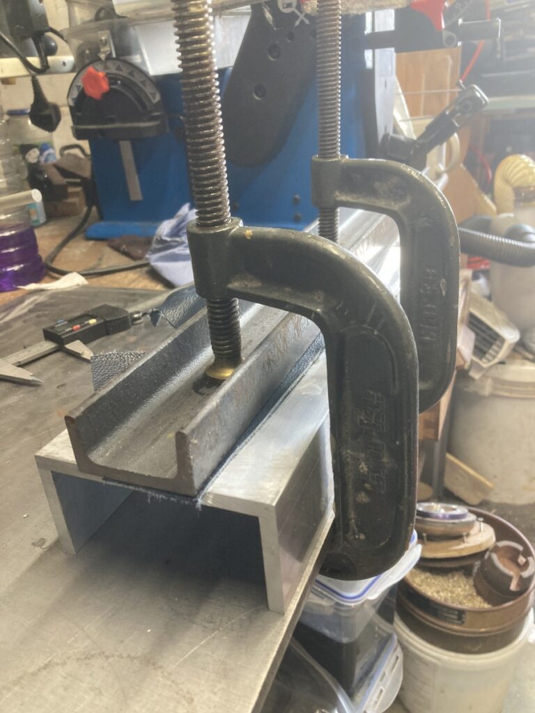
…but my clamps gave up before the aluminium:
Instead, I decided to make and fit all of the other bits and sort the back out later.
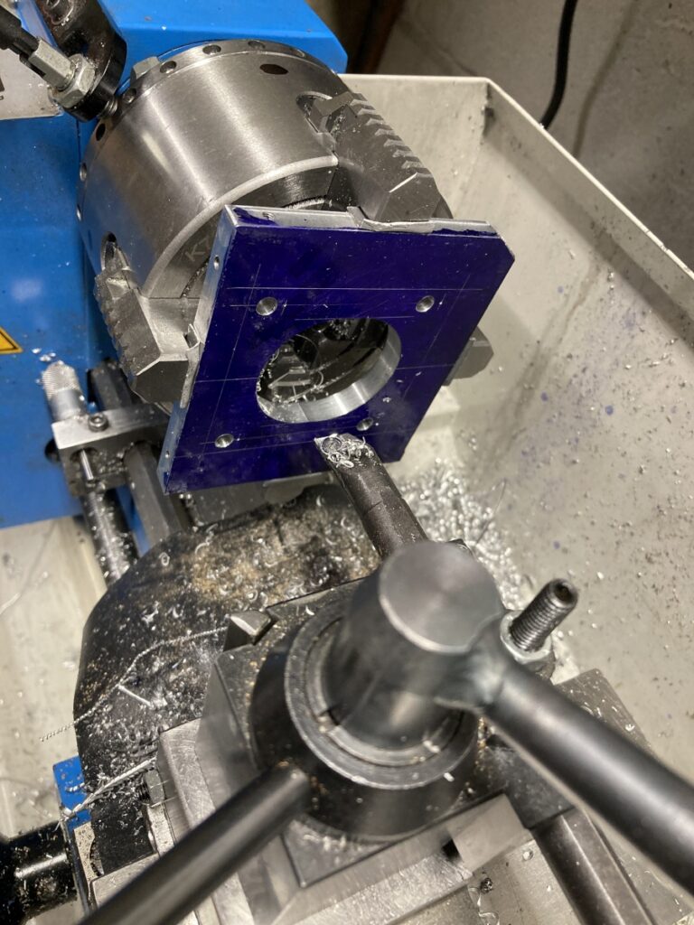
The supplied spindle mount was slightly too wide to fit inside the extrusion and needed to be machined down to be a tight fit inside the U section – I did this using the vertical slide on my lathe:
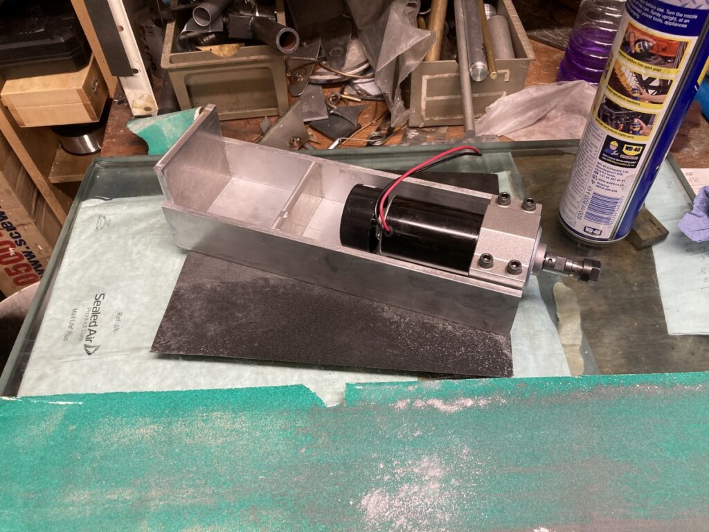
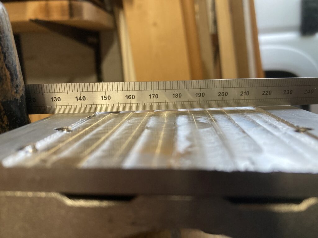
Fitting the spindle mount, a plate to mount the stepper motor and another horizontal plate helped to squared up the extrusion, but the back face was still bowed, especially at the edges where I wanted to mount the linear rails.
I spent some time trying to level the back face by rubbing it on abrasive paper on the glass plate.
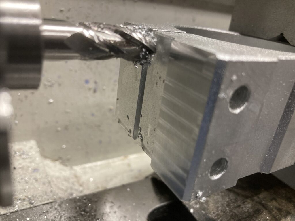
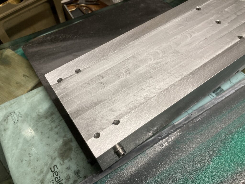
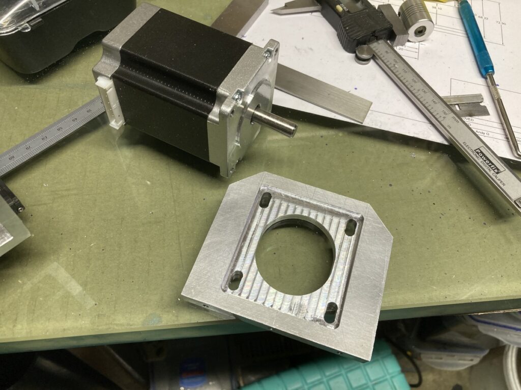
Although this was working, it seemed to be taking ages to get to the very edges of the part, so I resorted to using a woodworking bit to rout out the central part of the rear face to speed things up:
A bit hairy, but it had the desired effect
This made it a lot quicker to get the remaining surfaces flat
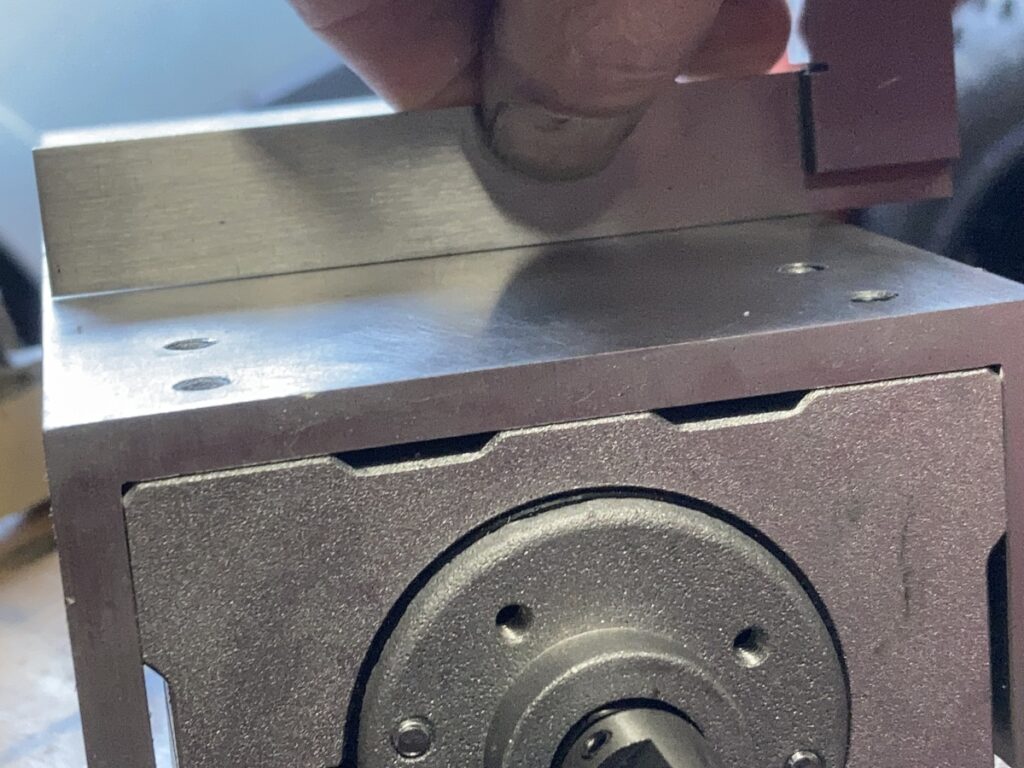
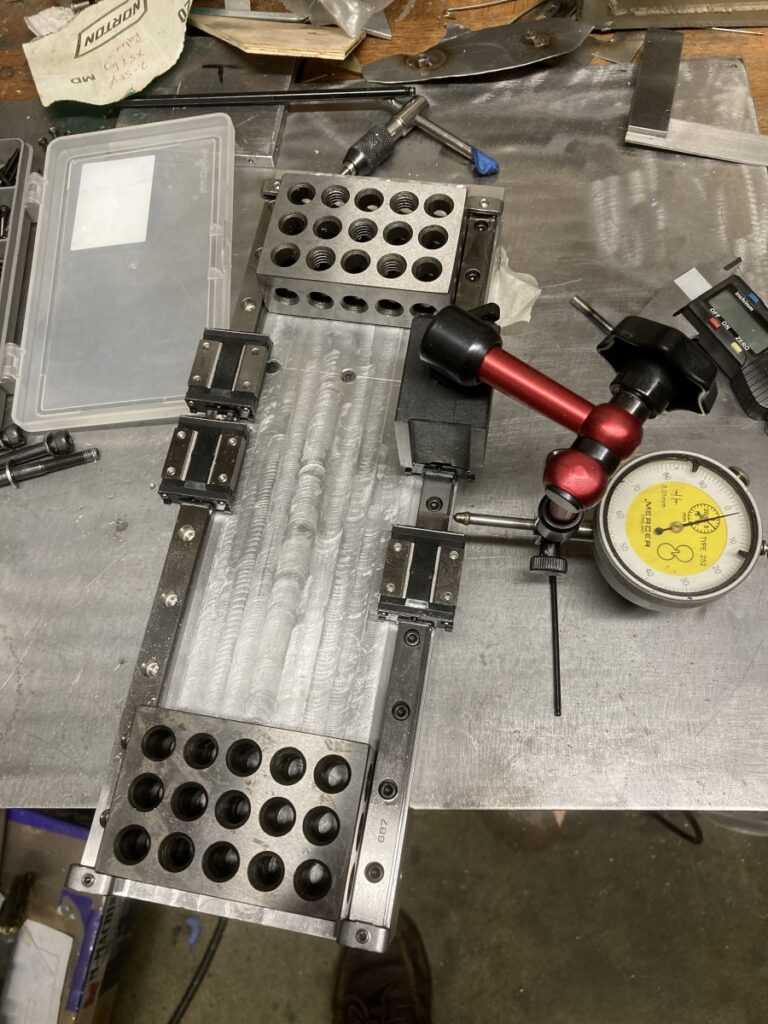
I could then align one of the linear rails wth the edge of the extrusion (using a dial gauge to get it parallel) and drill & tap its mounting holes
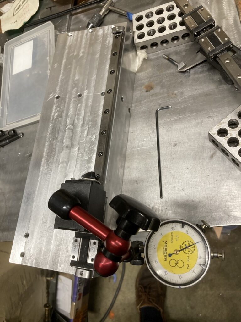
The second rail was fitted parallel to the first one using 123 blocks as spacers (two 12mm wide rails and a 76.2 mm long 123 block fit nicely onto a 100mm wide extrusion)
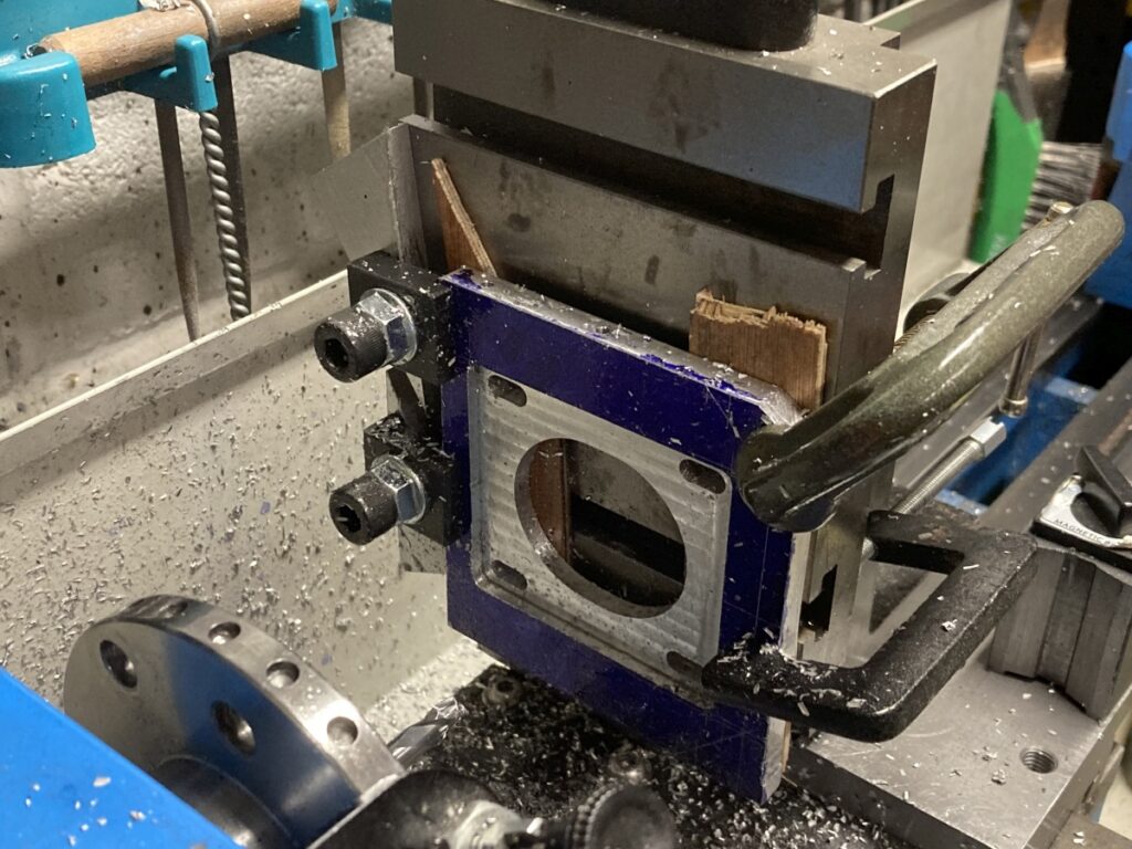
The stepper motor mounting plate was bored out on the lathe (two slightly offser bores to allow some adjustment) and then cleaned up and recessed using the vertical slide again:
The Z axis leadscrew is supported using a proprietary ‘BK’ style bearing block (from a seller on Aliexpress), but this couldn’t be fitted at this stage as it needs to be machined down to suit the exact spacing between the axis and its support plate once they have been assembled.