
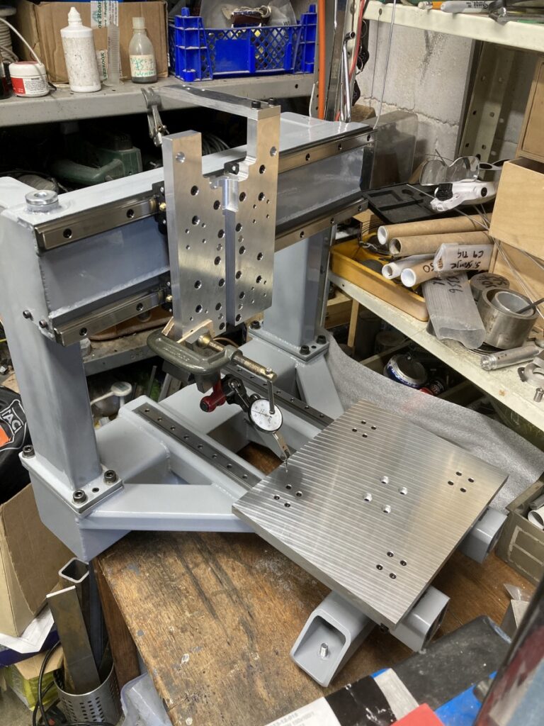
The Y axis carriage was made from an offcut of 12mm thick aluminium tooling plate (ex ebay). It arrived cut nice and square, so I could use the edges as a reference for laying out the holes for the Y axis cars.
Once the cars were fixed to the plate, I could use another edge on the plate (at right angles) to set the Y axis rails perpendicular to the X axis (just by clocking the end of the plate parallel to the X axis).
(Everything was just being roughly squared at this point.)
The linear rails are the Chinese ones I’d ordered originally (12mm x 300mm). I’d have liked them to be a bit longer and a bit heavier (even 15mm), but as I already had them, and was trying to do this on a shoe-string, it seemed a waste not to use them.
I had trouble with the carriage binding when I tightened everything up initially, which I eventually traced to the Chinese ball bearing cars being different heights:
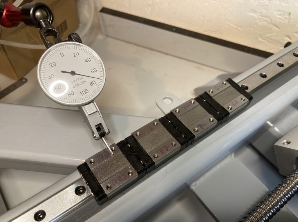
I’d bought a pair of rails with 1 car each plus two spare cars from the same listing on Aliexpress. The heights depended on which rail they were mounted on, and also which way around they were fitted. By swapping them between rails and turning them end-for-end I eventually found a combination that was near enough that the carriage would run smoothly without binding. The tooling plate offcut also had a slight bow to it which didn’t help. (Any height difference side to side wasn’t really important as I would be aligning the gantry to the Y axis eventually.)
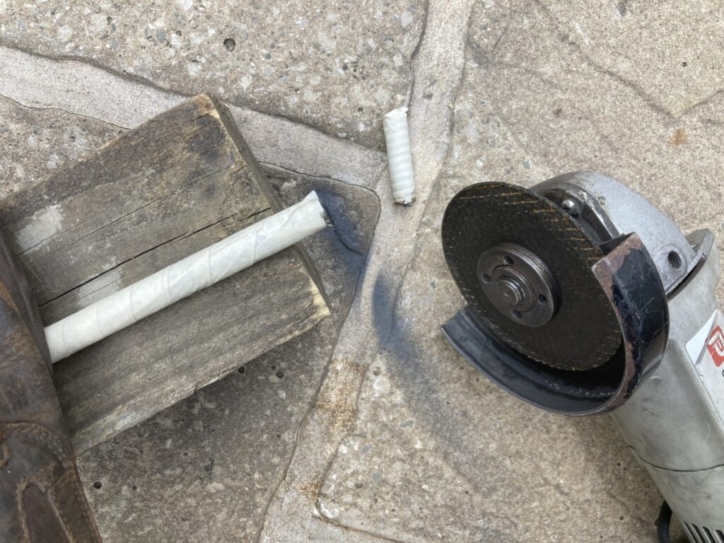
I’d already ordered a leadscrew for the Y axis on spec, and as it turned out, it was too long.
Easily lopped to length with the angle grinder
Turning the end down to take the support bearing was a bit much for the mini lathe – the intermittent cuts on hardened steel turned it into a bit of a rodeo, and not something I’d like to make a habit of. That stuff is HARD!
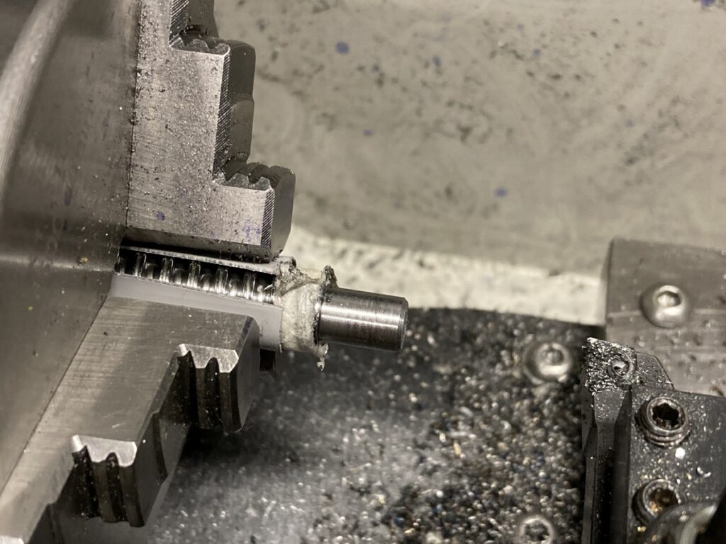
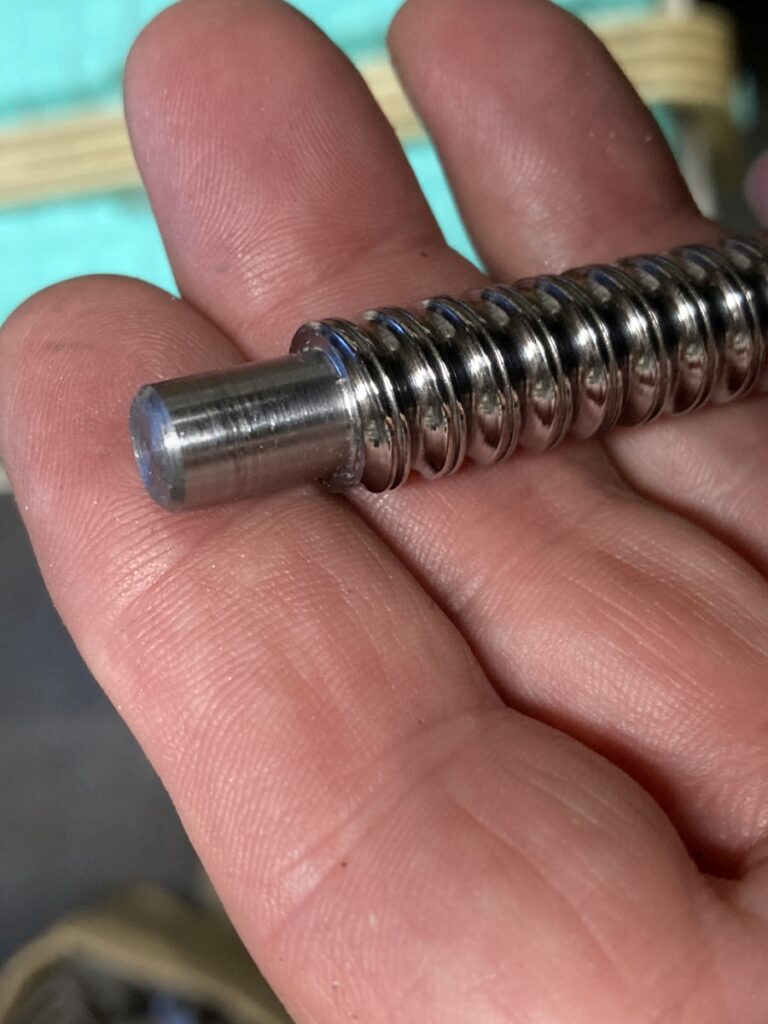
I tried to cut a circlip groove in it using an HSS tool, but it (quite literally) didn’t even scratch the surface. I eventually resorted to cutting the groove with a hacksaw.
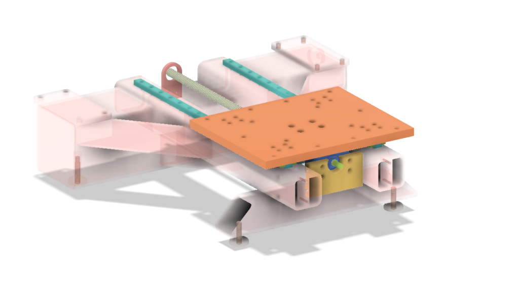
A a nice, parallel packing piece was needed to make up the space between the ballscrew nut and the underside of the carriage (still a space in the photo) – this was just faced to length in the lathe.
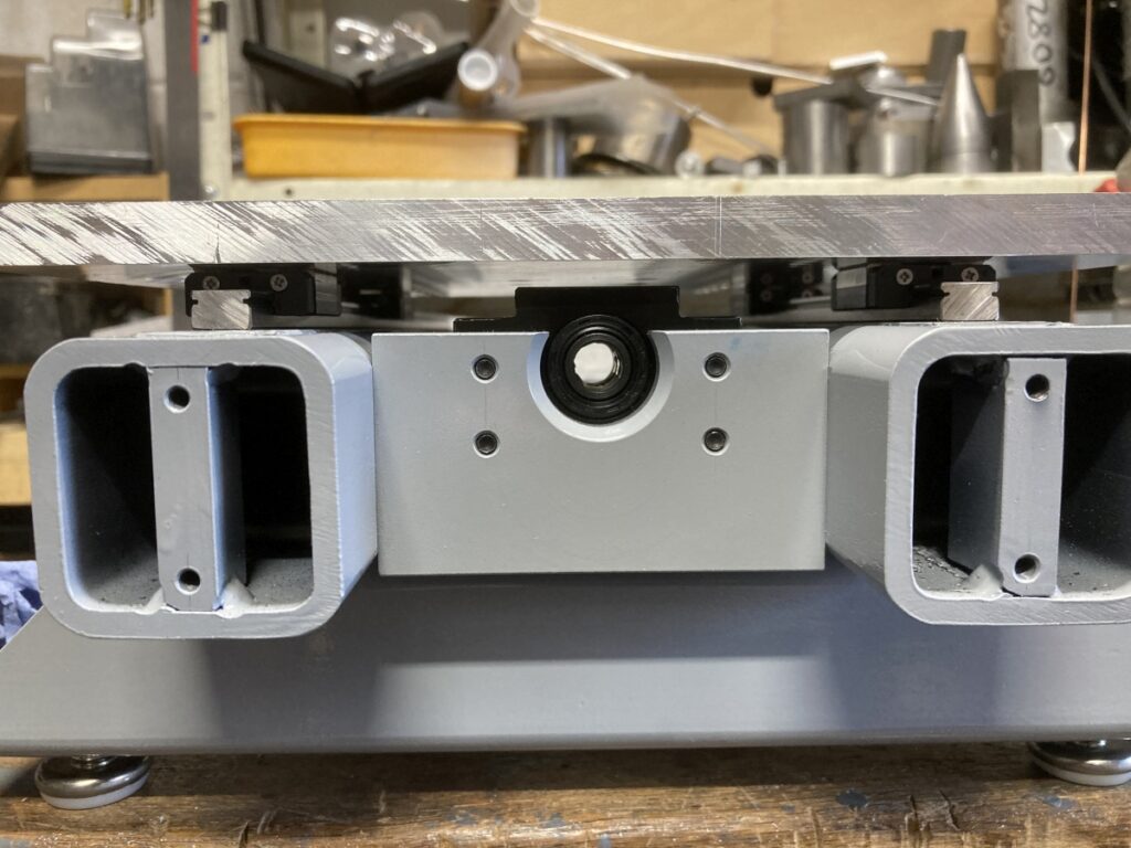
The support bearing for the end of the leadscrew was similar to the X axis one (the bearing inner race can slide on the leadscrew to allow for length changes, etc. while still holding it steady about its axis).
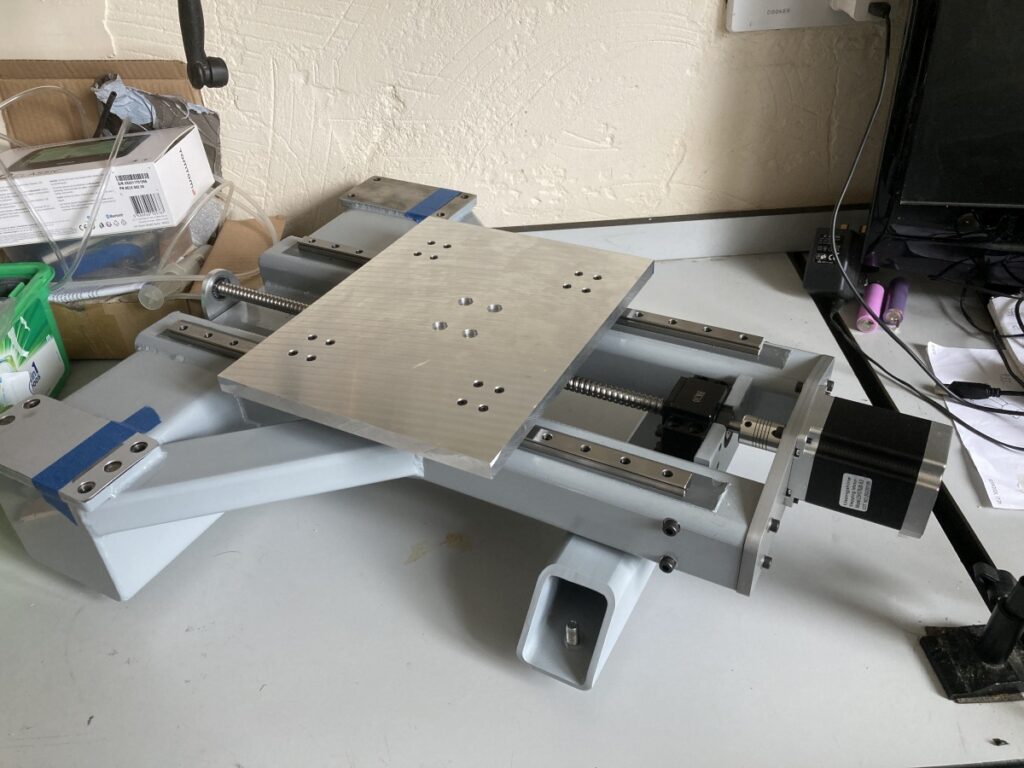
The Y axis assembled
And that was the major bits all made.