
The floor in the load area of the van is lower than the floor in the cab so when you swivel the seats around, you’re left with your legs dangling in thin air. To avoid this, we decided to add a raised ‘plinth’ behind the seats.
We mocked it up at a very early stage and found that it needed to be about 150mm high, which ends up being level with the rear of the cab floor (the cab floor slopes downwards between the seats).
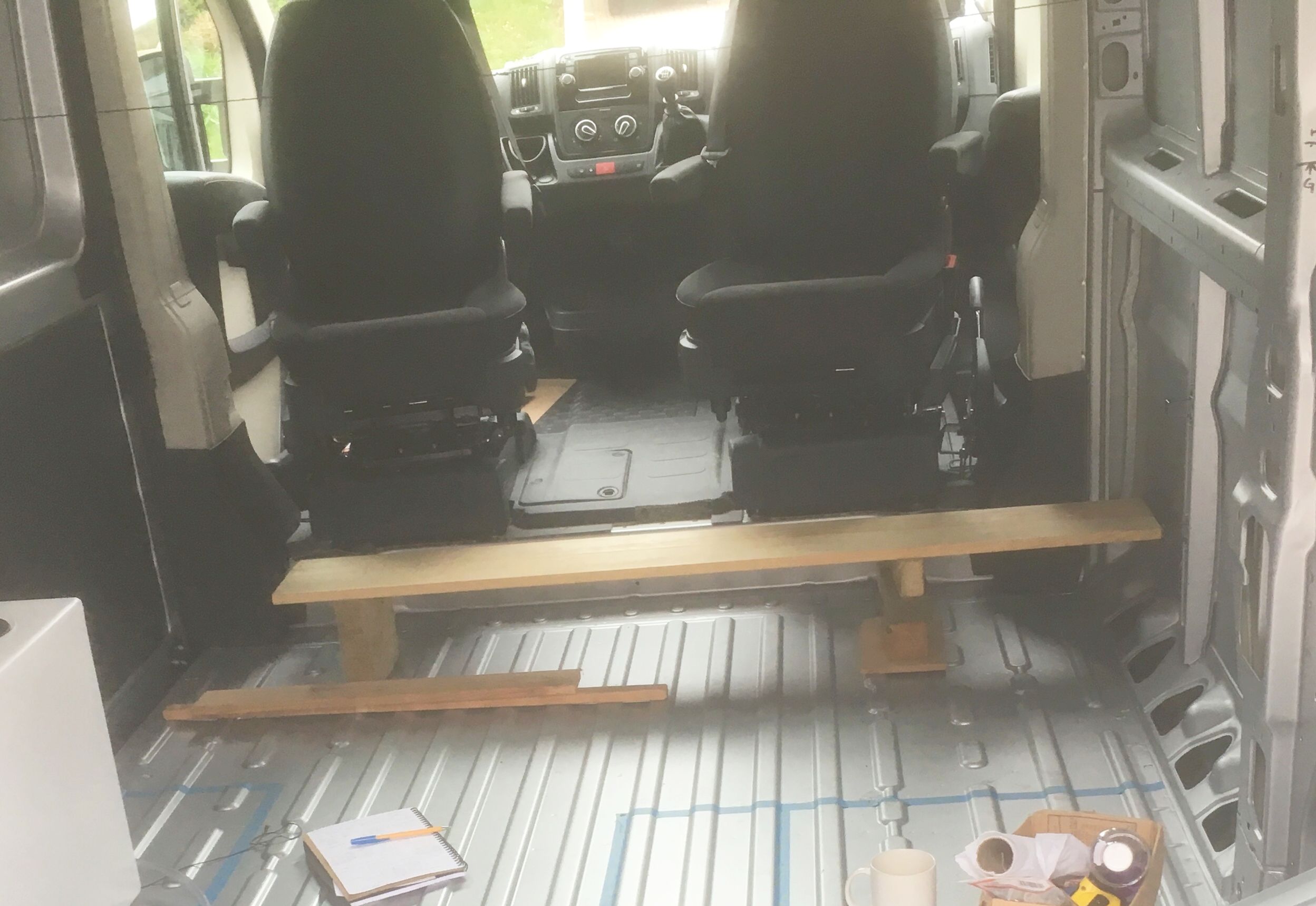
I order to give enough area to be comfortable, but leave enough space to get into the van, it would need to taper towards the side door. We let it at that and got on with the rest of the van.
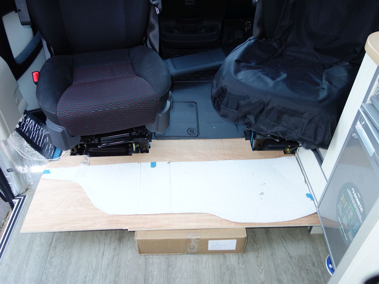
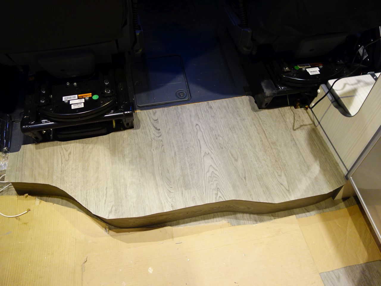
Once we’d got the floor down and sorted out the units on the driver’s side, it was time to come back to the plinth and figure out how to make it.
I cut a piece of ply to match the shape of the rear of the cab floor and the units, then we sat in the seats for a bit, shuffling our feet and drawing lines until we’d refined the shape and from this created a paper template that would give us a reasonable area to rest our feet on and also some room to get into the van.
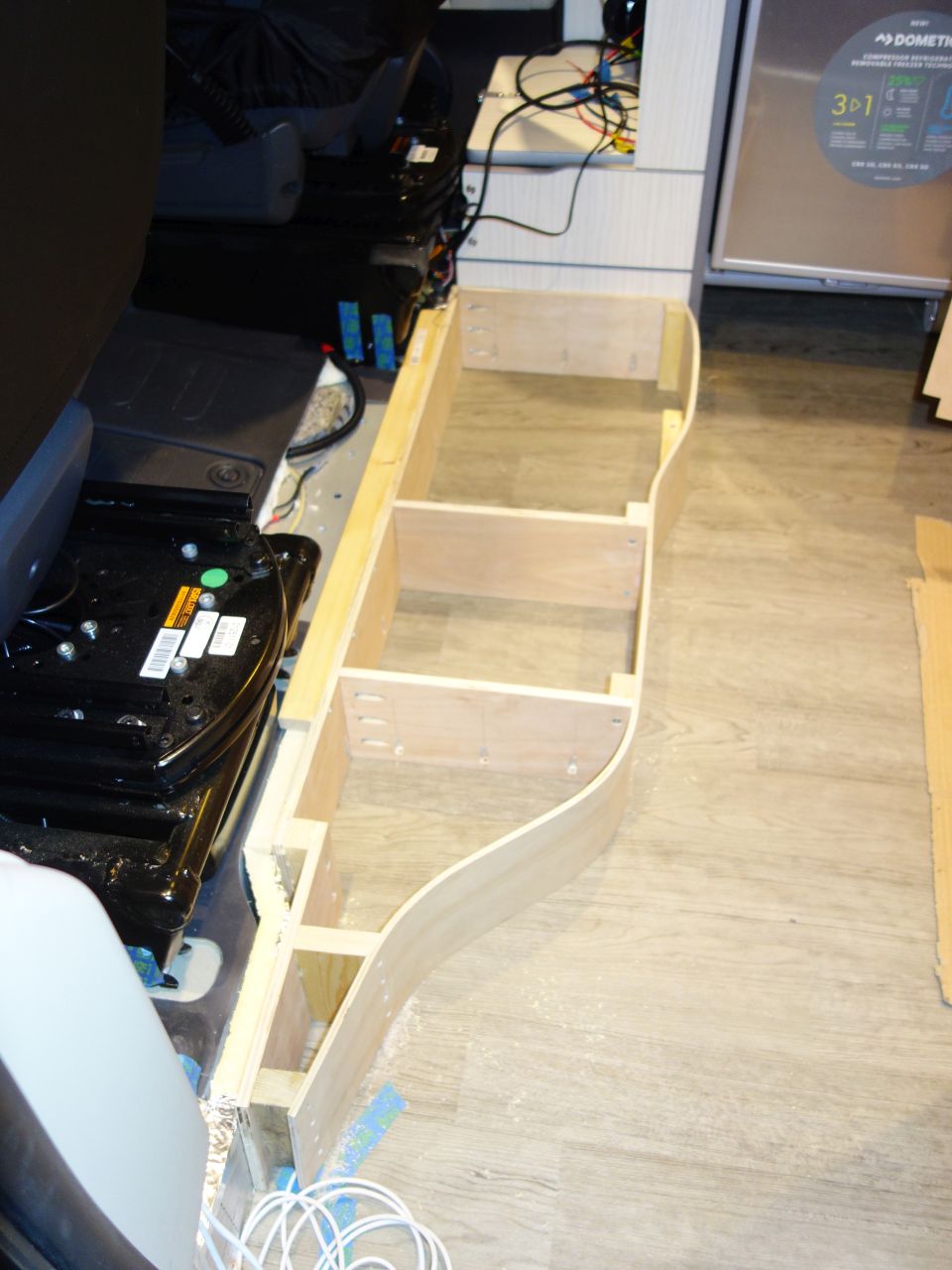
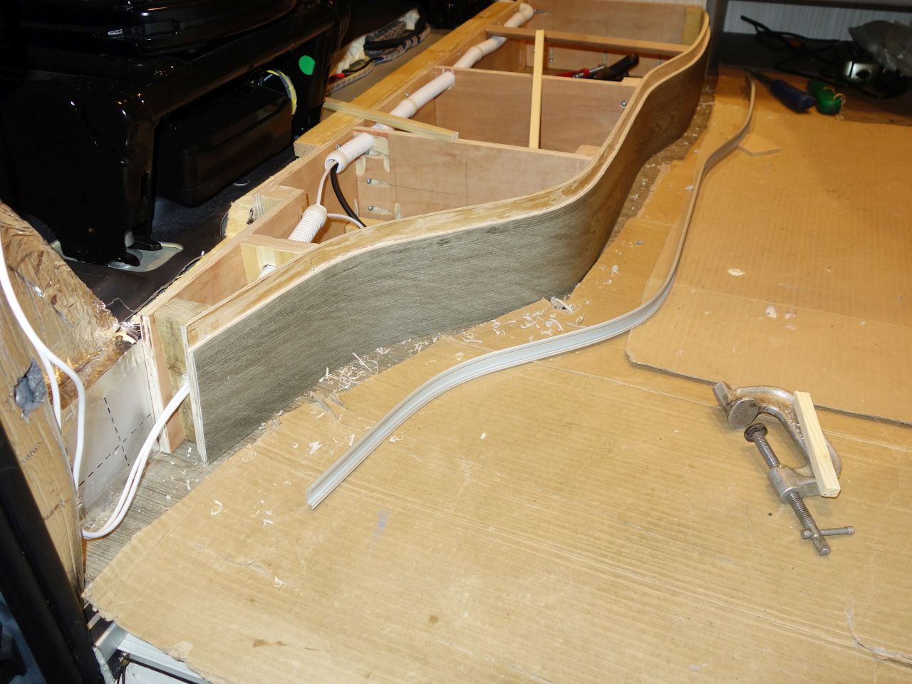
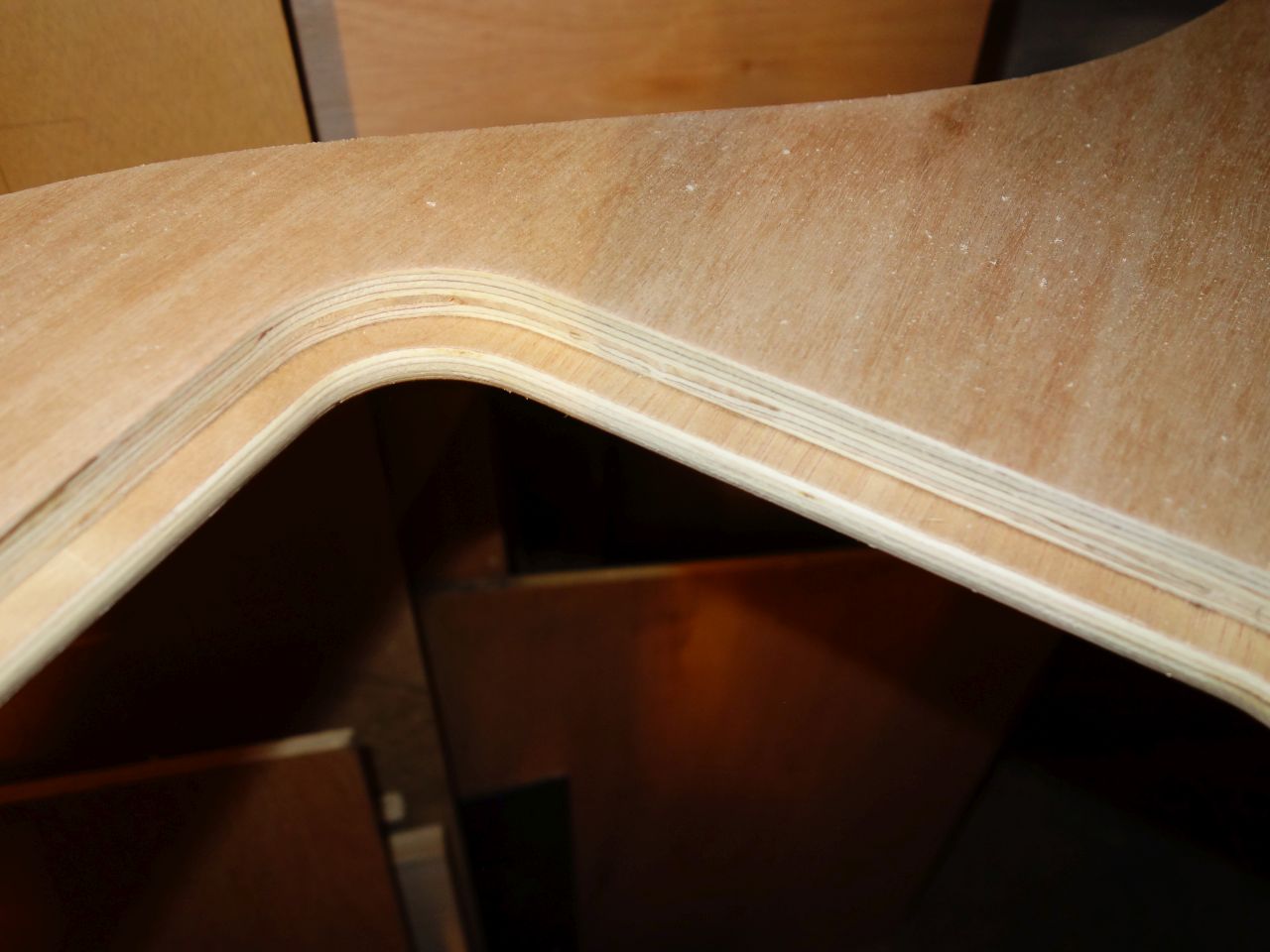
The rear edge of the plinth was made by laminating a couple of strips of 4mm ply inside a pair of MDF moulds (shaped to fit just inside the edge of the template).
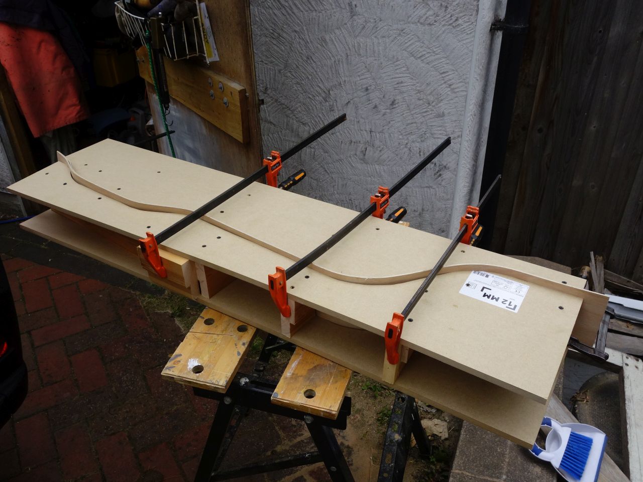
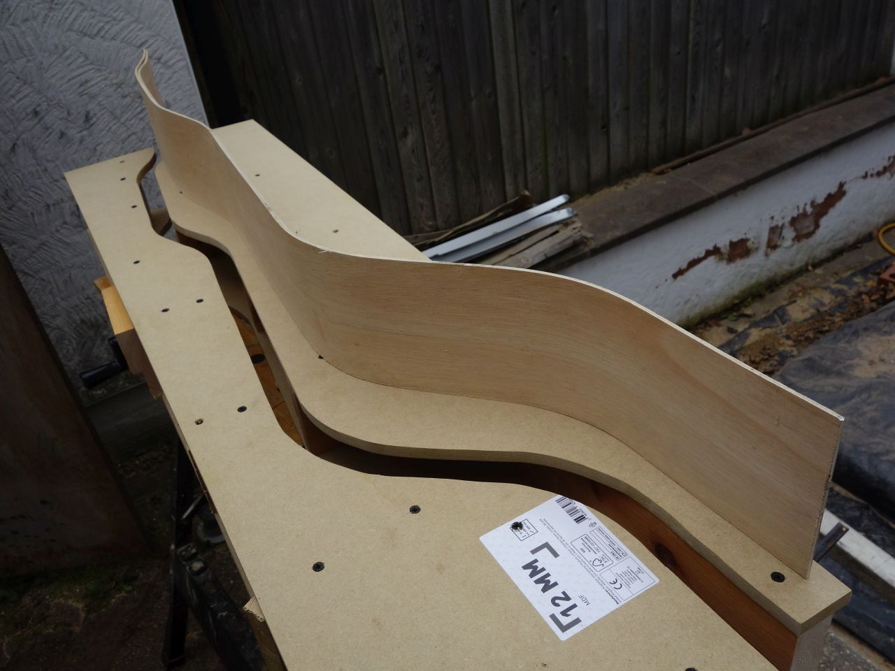
It didn’t exactly match the mould, but it was close enough!
The edge and plinth are supported by vertical 12mm ply dividers. After a bit of experimenting with the best places for these to get the shape right, they were fixed through the flooring with pocket hole screws and the laminated wall attached to them.
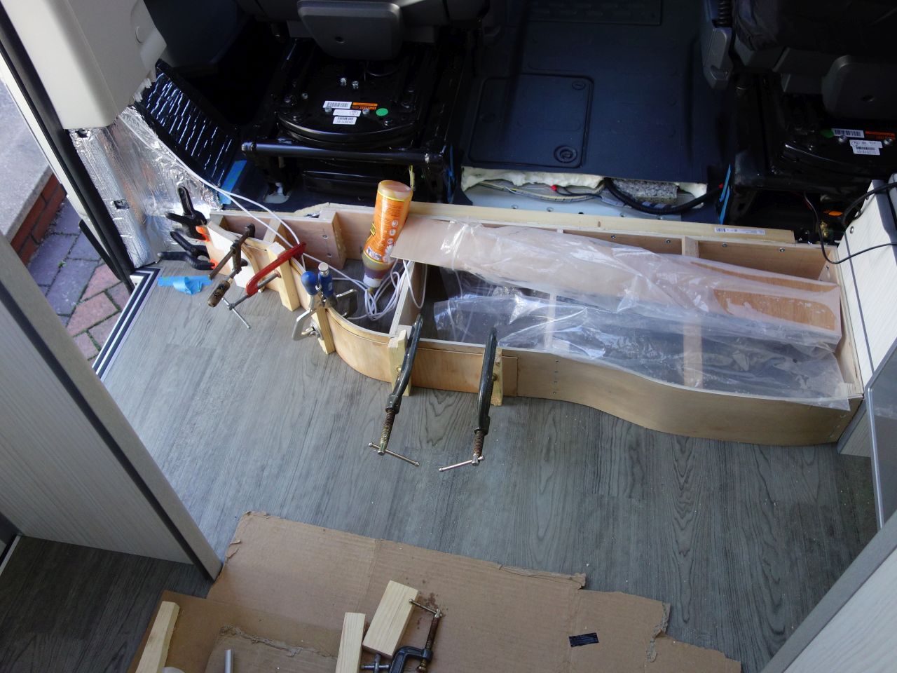
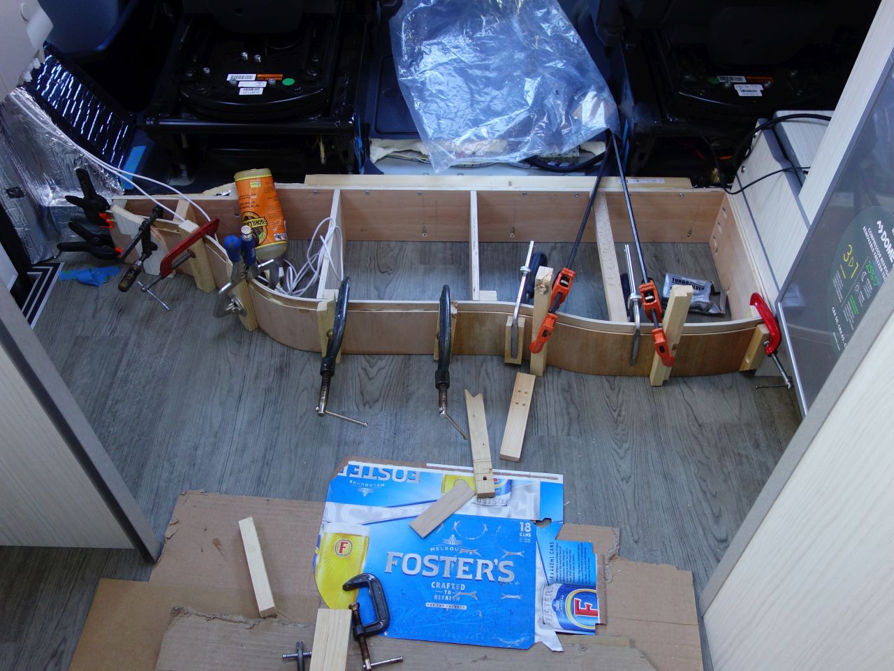
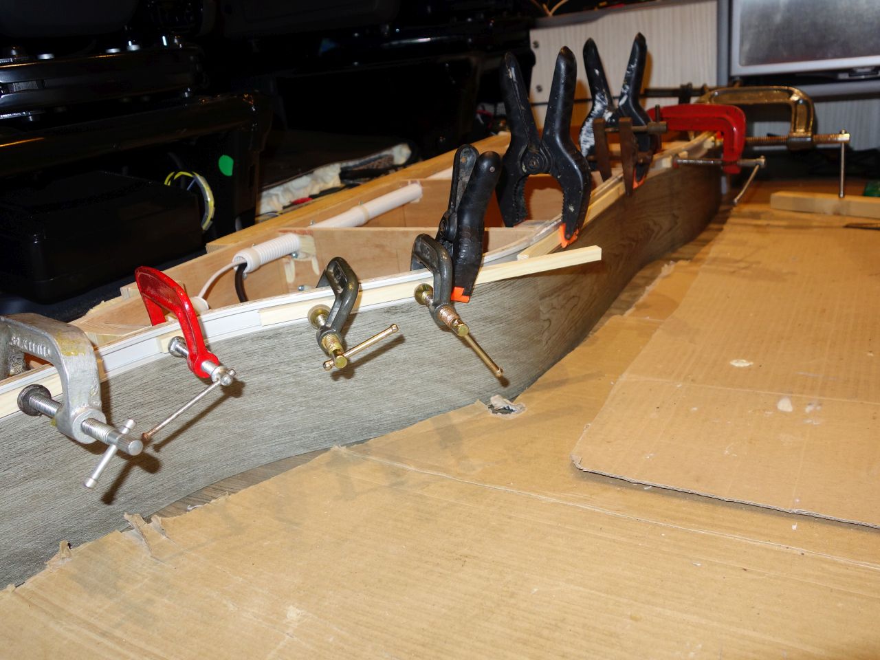
A further strip of 4mm ply was laminated in-situ after soaking. (The beauty of the polyurethane glue is that it loves sticking to wet wood.)
Half of the wall has been laminated here, and the next piece is still sitting in the polythene bag where it has been soaking:
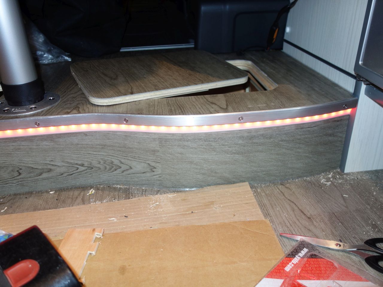
The top layer hides the screw heads. It is deliberately shorter than the first two layers to leave a recess for fitting an LED lighting strip later on
I finished the rear wall with a strip of Altro flooring to match the rest of the floor. (My OCD would have preferred a vertical grain, but I didn’t have a piece wide enough!)
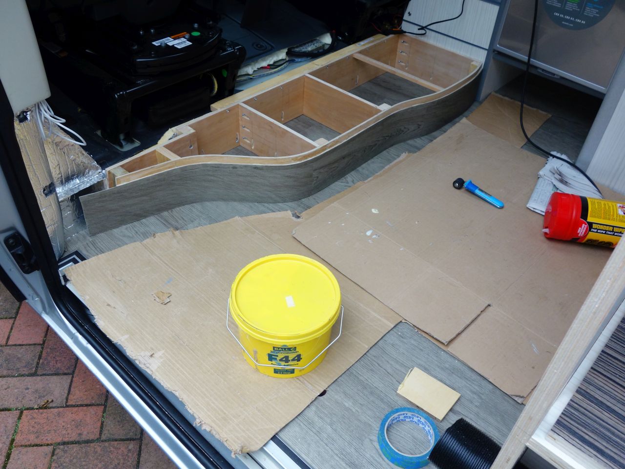
I could then bend the channel for the LED strip to shape and stick it into place with Stixall, which finished off the edge of the Altro neatly.
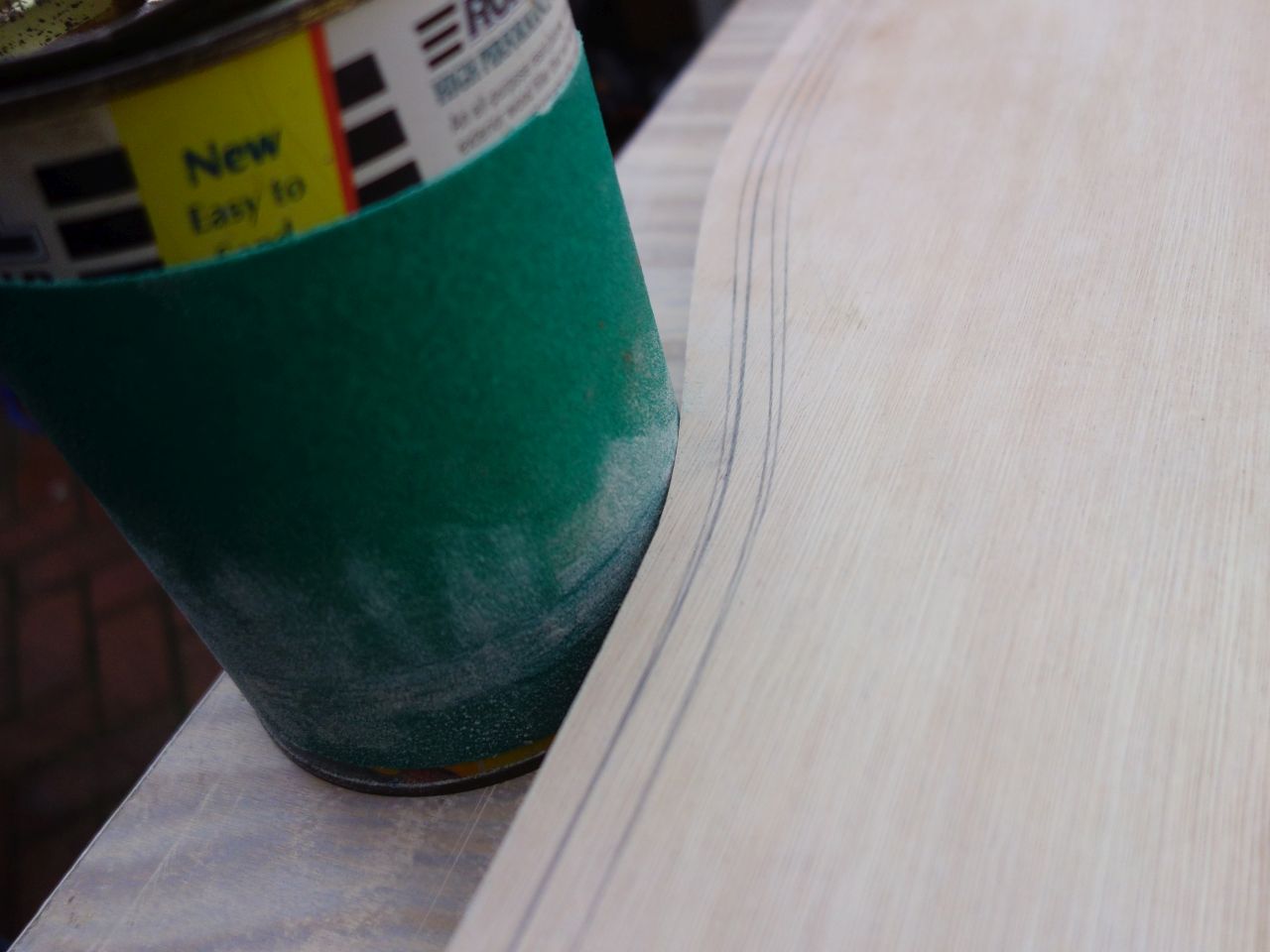
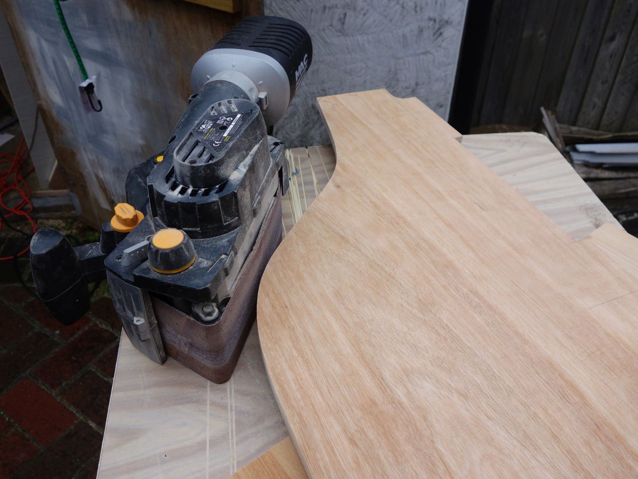
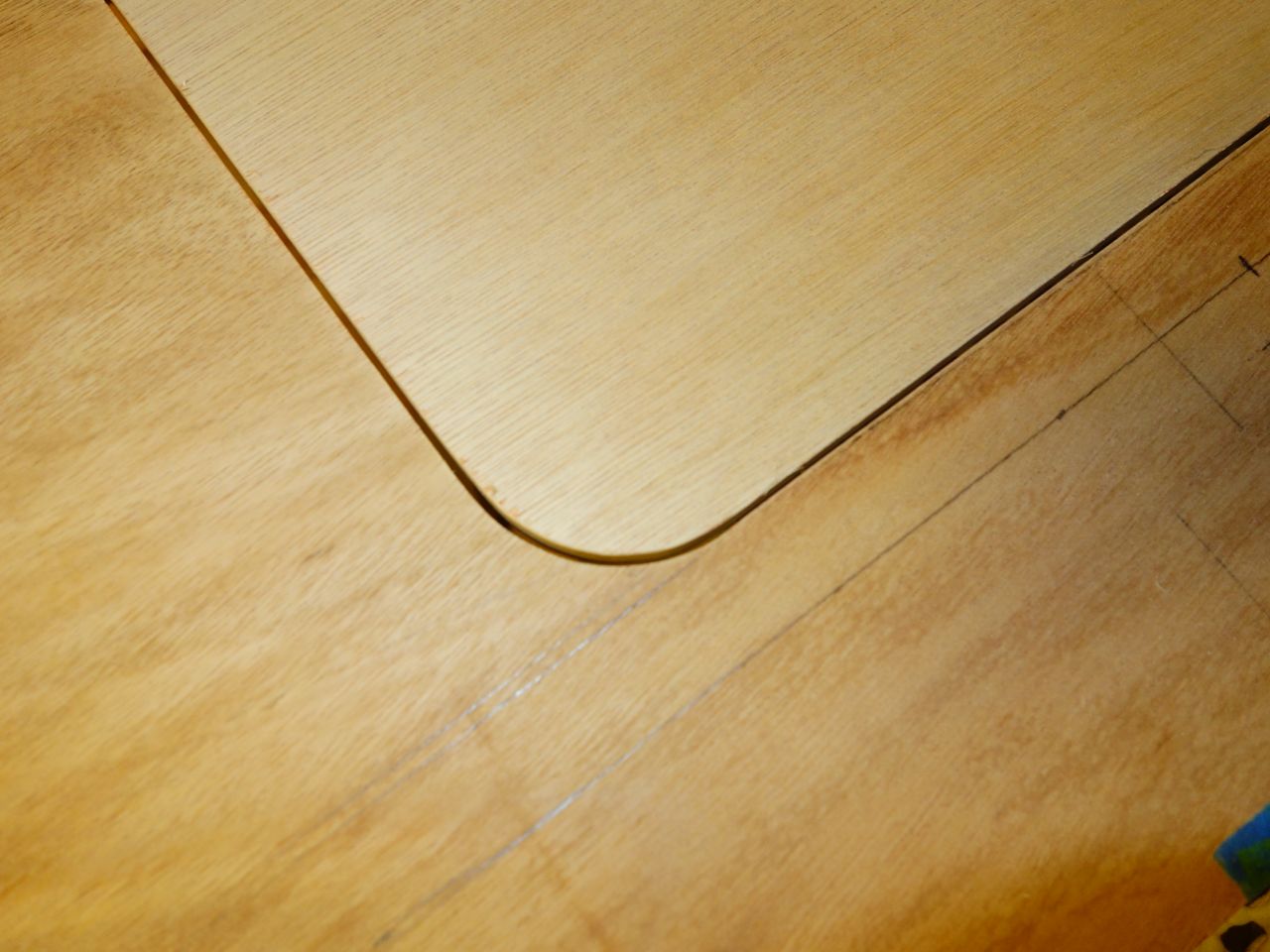
Once the shape of the plinth was finalised, I could mark out the 12mm ply for the top using a washer around the pencil to create an offset…
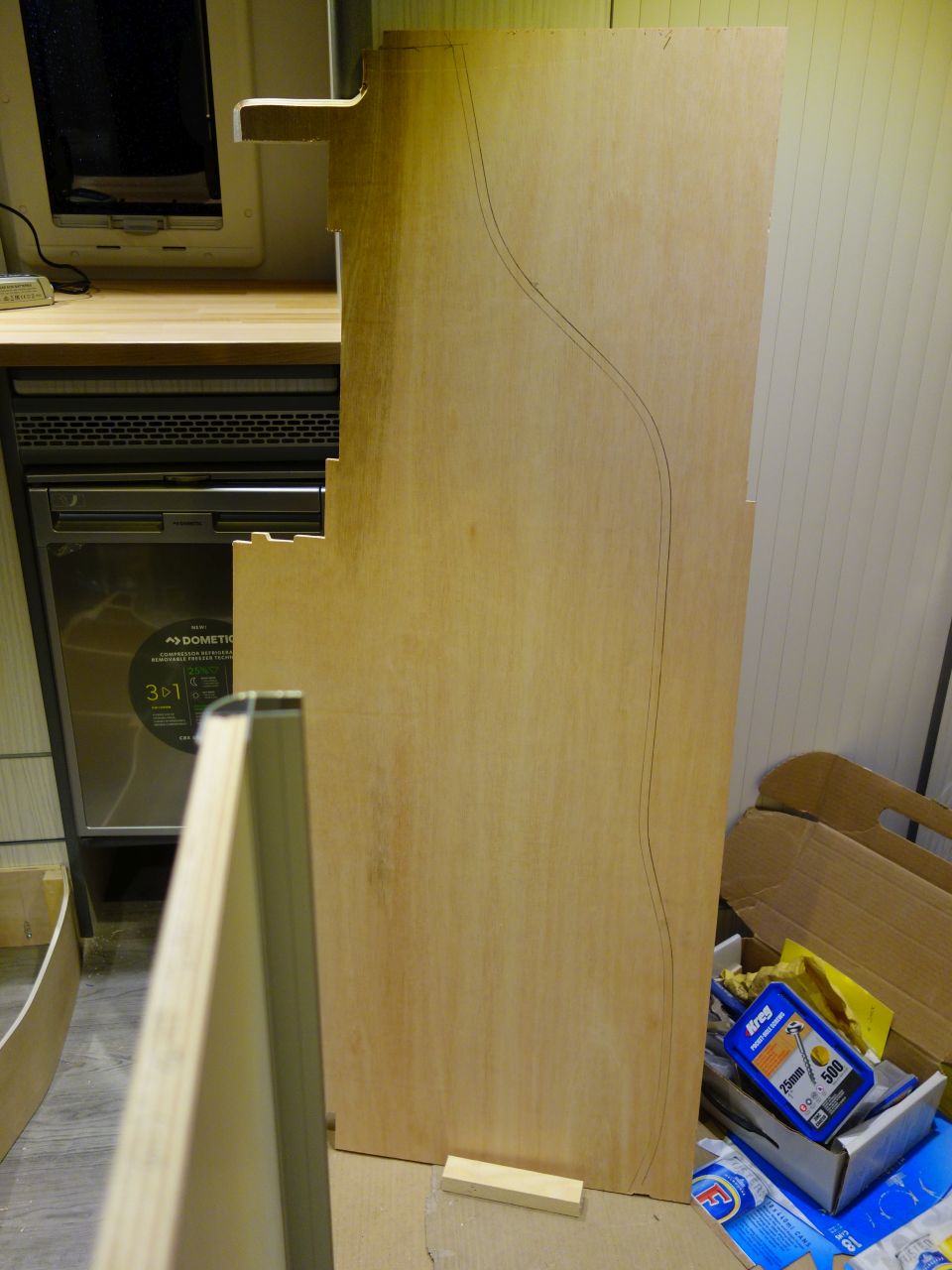
…and then cut it to size and sand it using a the poor man’s spindle sander (paint tin with sandpaper wrapped around it!) – although the belt sander worked OK for the convex bits.
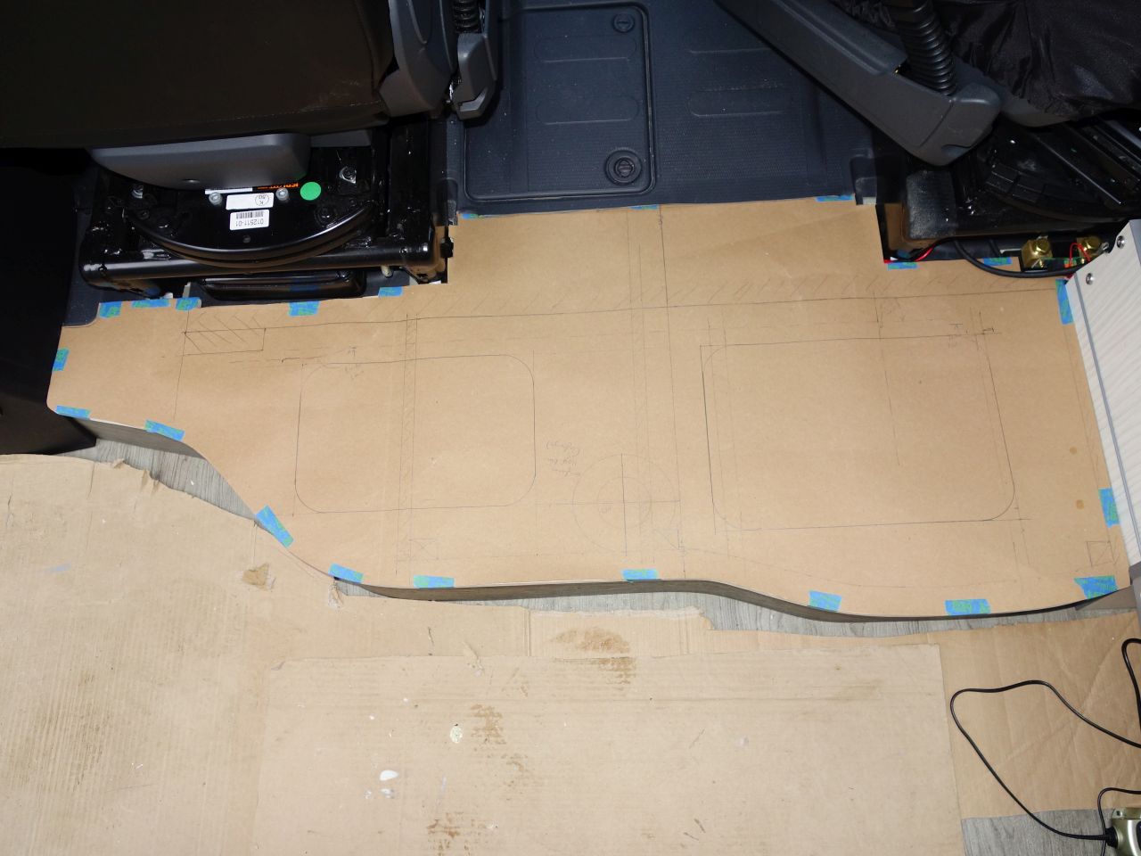
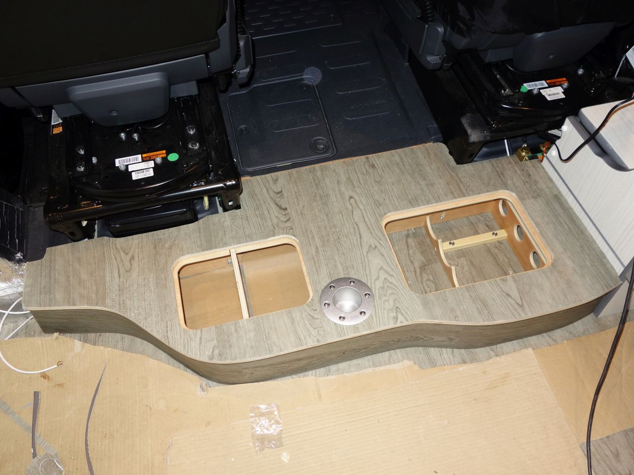
Then it was more CAD (cardboard aided design) to decide on the hatch and table leg positions, avoiding the obstructions underneath:
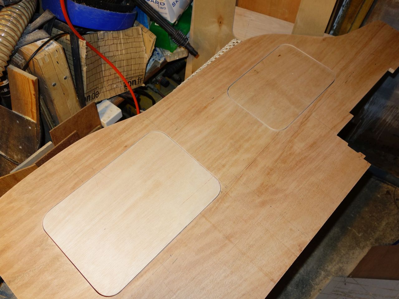
I wanted rounded hatches, but wasn’t sure how to cut them out and leave an even gap. In the end I came up with a convoluted scheme using different sized router cutters and collars. In hindsight, square hatches would have been a *lot* easier.
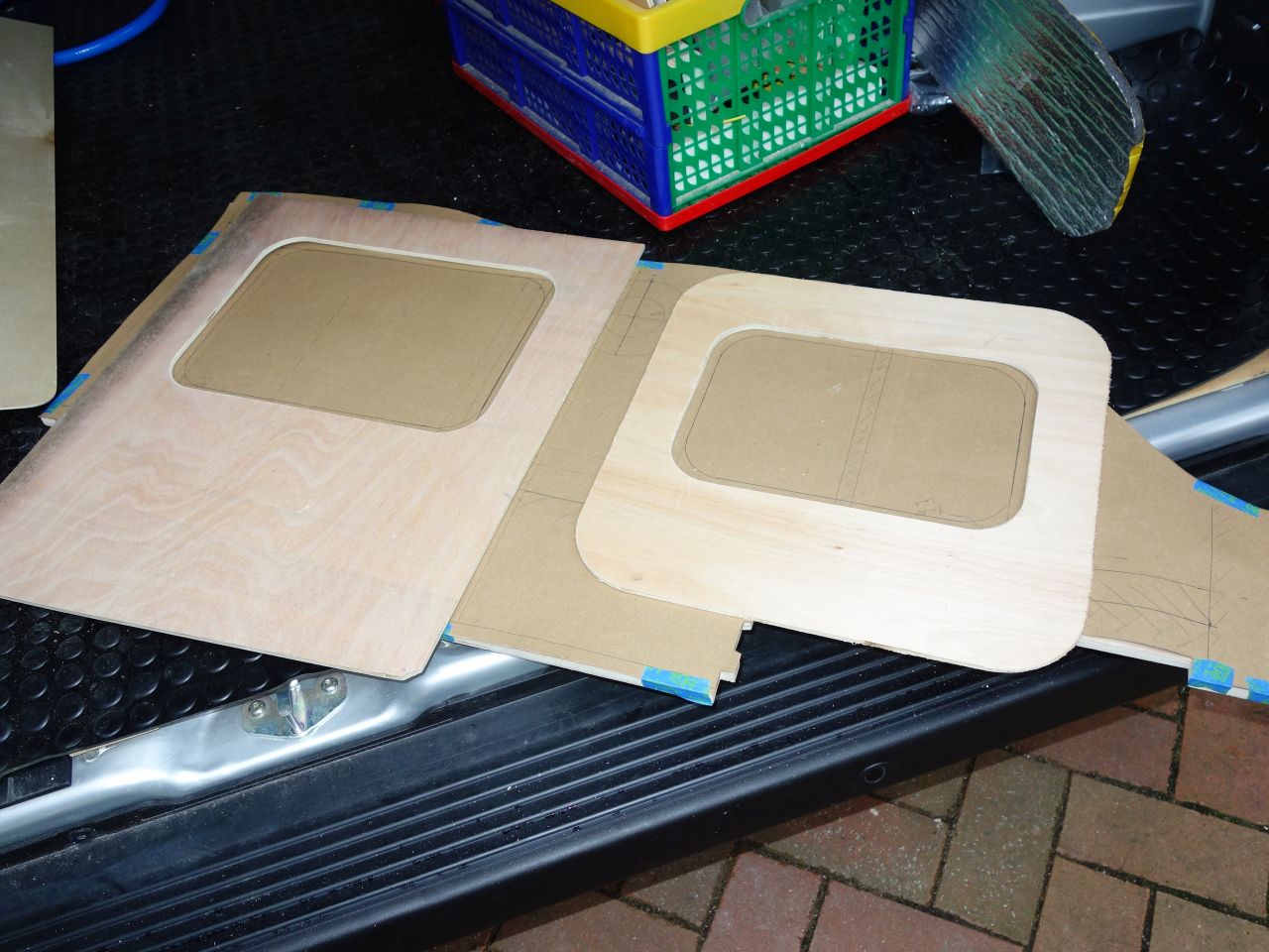
1) Make master templates for each hatch opening, sized so that a router with a guide collar is centered over the finished hatch line:
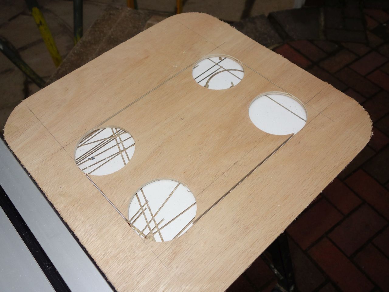
These are the templates laid over the paper pattern (the offset between the template and the pattern is the radius of the router collar that will be used when cutting the next set of templates).
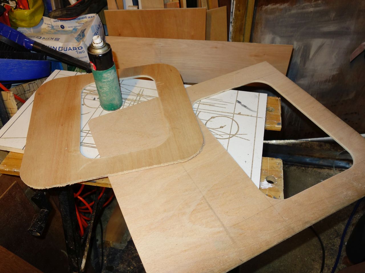
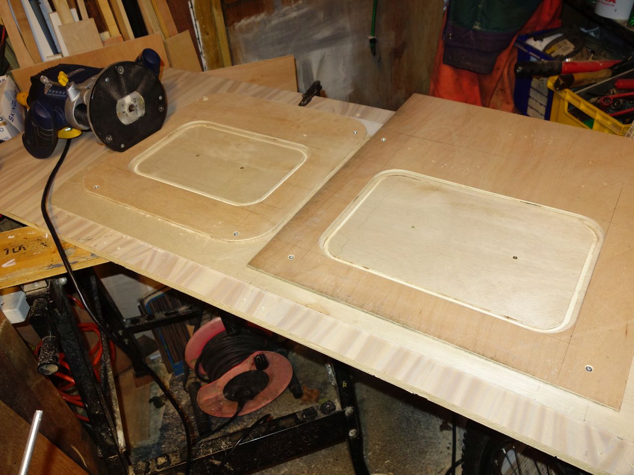
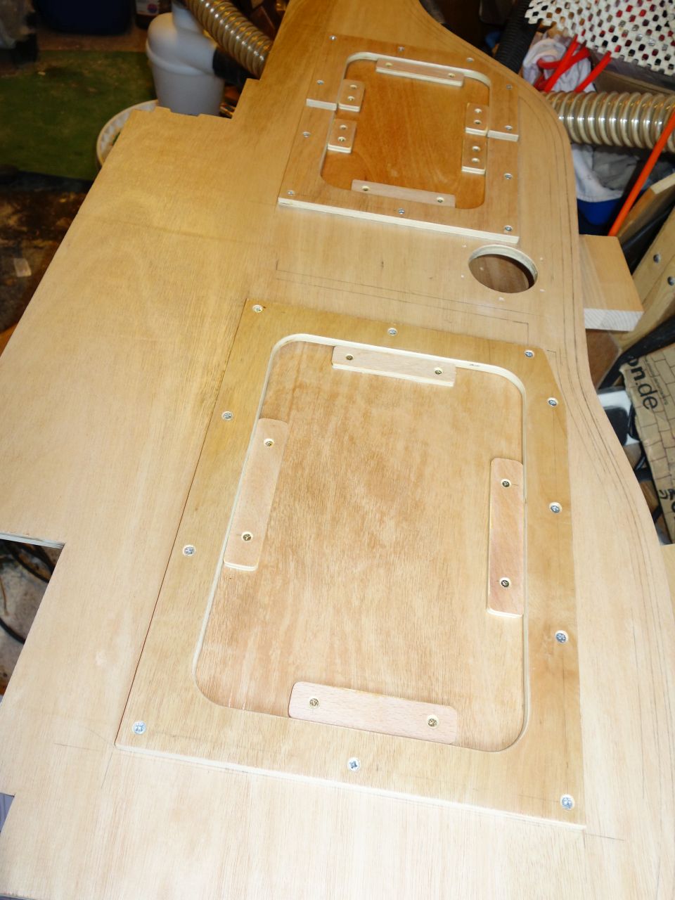
2) Cut a second set of templates from these using a 1/2″ wide router cutter. This gives an internal and external template for each hatch that is ~6mm offset from the finished edge of the hatch (actually 1/4″ – half the cutter diameter) – here the first set of templates are on top and the second set of templates have just been cut. You need to be quite careful to keep the router tight against the first template since both parts of the piece underneath will be needed.
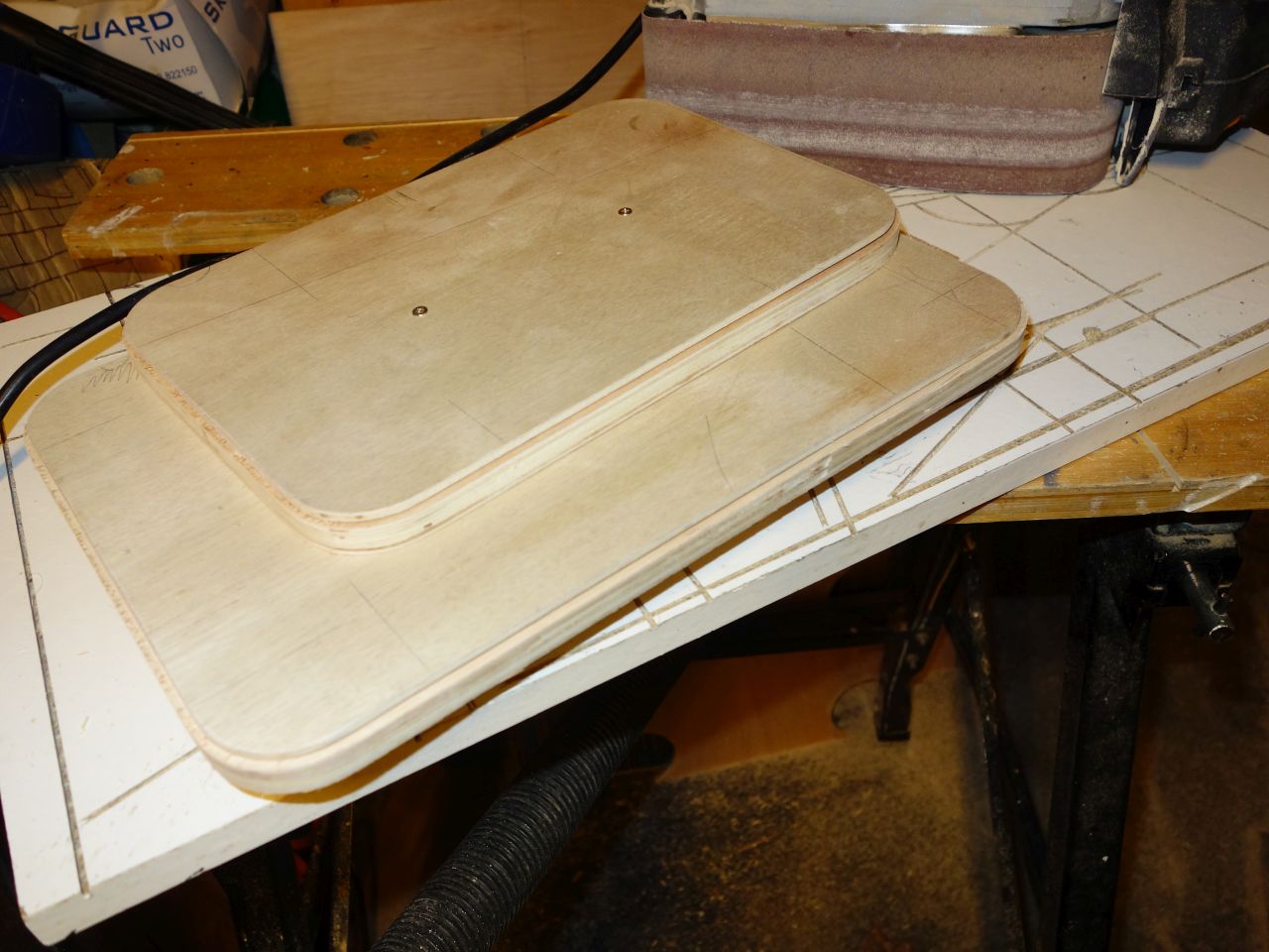
3) I used the external templates to cut out the hatch covers and the internal templates to cut out the floor. In each case, I used a 6mm cutter with a 17.7mm guide collar (odd size, but it’s what came with the router…) which creates a 5.9mm offset between the cut and the template. (So the hatch is 5.9mm bigger all round than the template which is itself 6mm smaller all round than the final size. Likewise, the hole is 5.9mm smaller than the template which is itself 6mm bigger than the final size!).
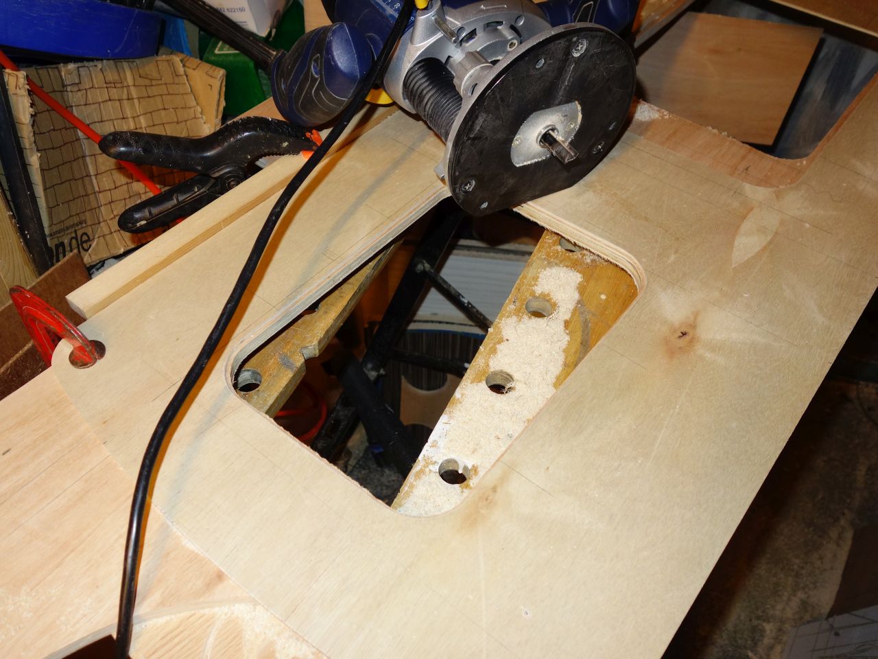
Cutting the hatches:
And the holes:
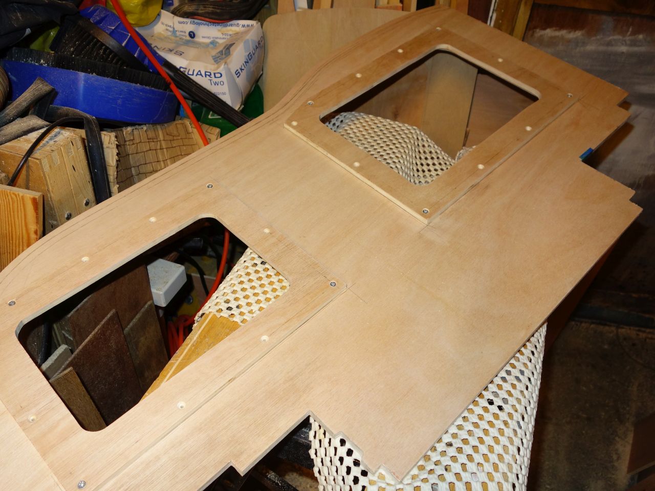
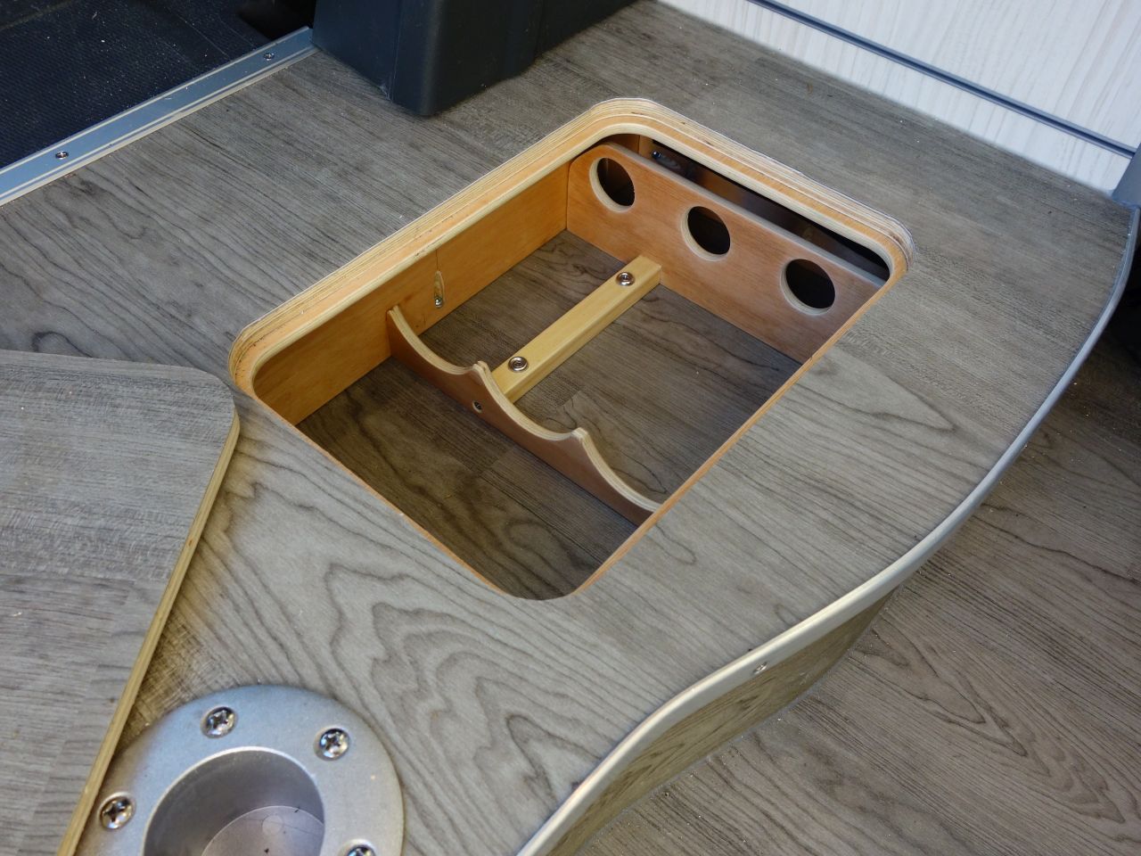
The proof of the pudding:
I was very pleased with the way it worked. I was very tempted to go back and make some interesting shaped hatches- like a moon and a star, or something.
The openings in the floor were used as yet another set of templates to cut a hole in some 9mm ply to create a shelf for the hatches to sit on which was glued and screwed to the underside of the floor.
I found it necessary to fix scraps of ply under the hatches to keep them centred in the openings.
(The smaller hatch fits over a badly placed support, so needed a notch in the ‘shelf’ to clear this. I’d intended cutting the support away before fitting the floor, but realised too late that I’d painted myself into a corner with the way I’d fastened it in, and I could no longer get it out to work on it – oops!)
I had a bit of wiring to finish off under the plinth and some blocks to fit so I could screw the floor into something:
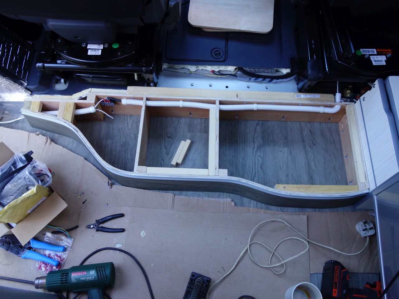
(The white conduit carries the wiring for the LED strips around the van, and the courtesy light wiring to the ‘elephant’s foot’ for a step light.)
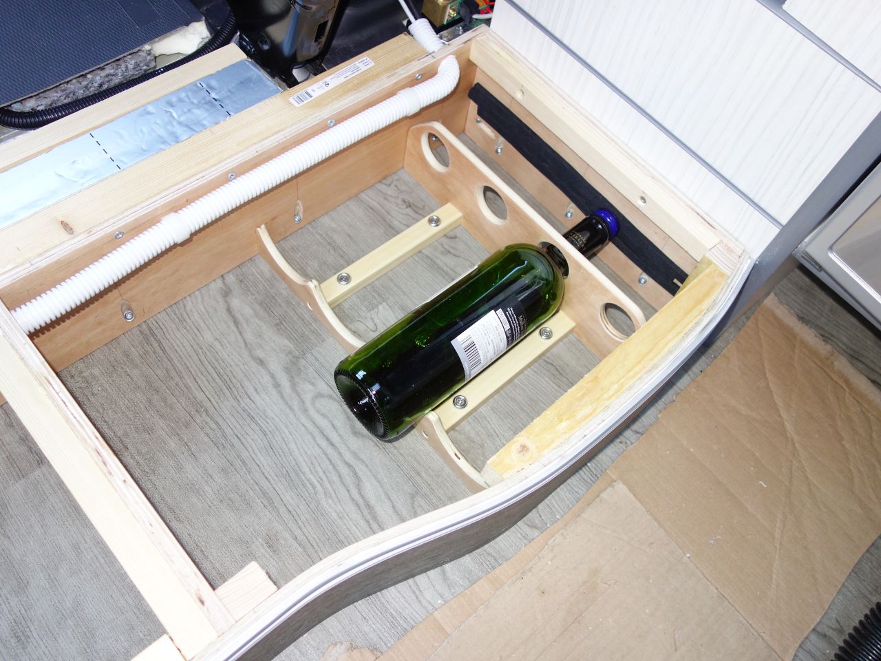
I also added some ‘custom’ storage – our wine cellar !
Then I could screw the floor down:
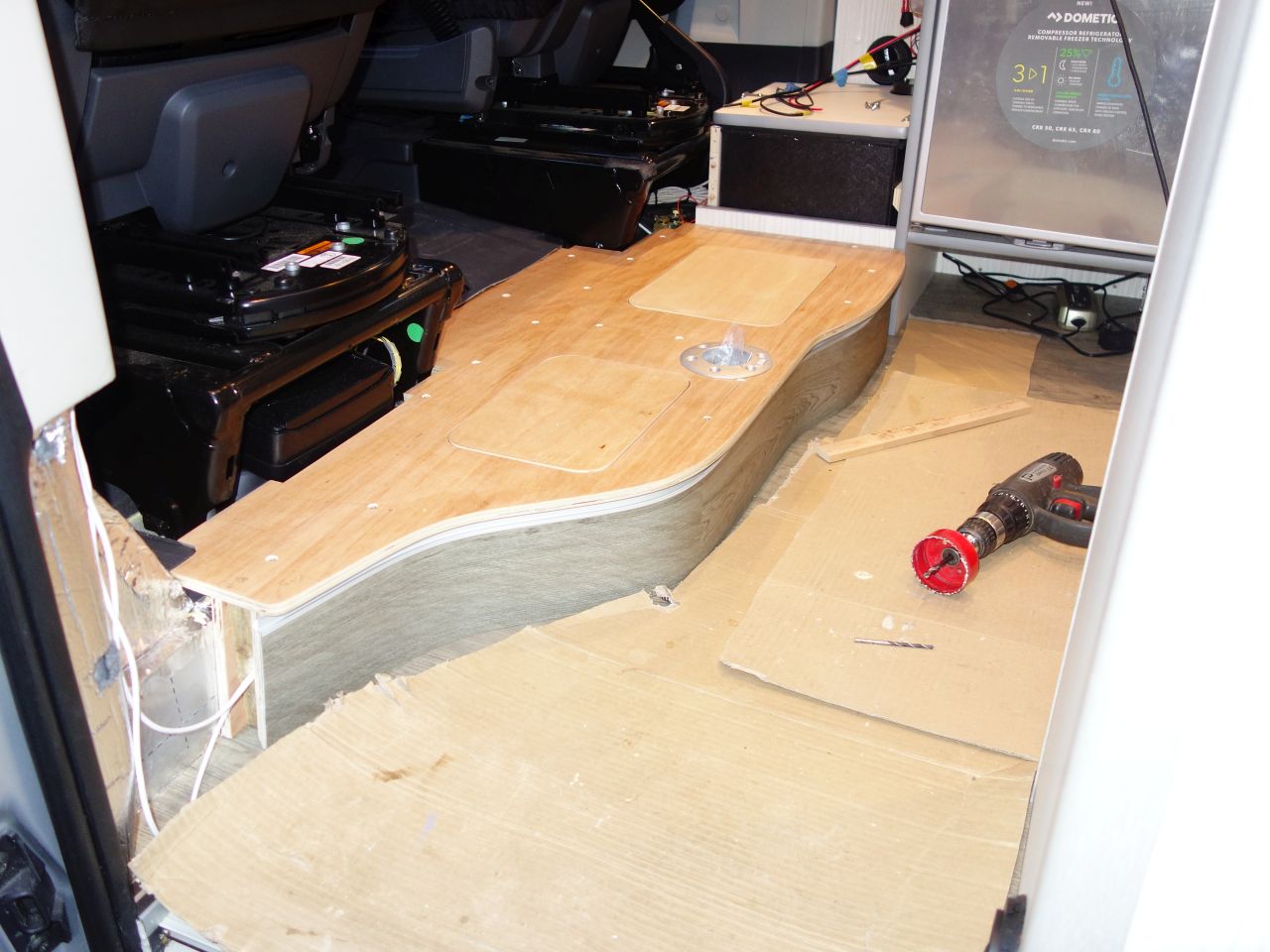
(The rough looking end nearest the camera is shaped to fit around the plastic ‘elephant’s foot’ trim that fits at the base of the ‘B’ pillar.)
I wanted the pattern on the floor covering on the hatches to match with the floor around them. This is where it all went a bit awry….
I decided that the best way to achieve this was to cover *everything* and then cut around the hatches later.
It started OK:
…but I made a bit of a mess cutting around the hatch corners – I was trying so hard not to clip the corner that I ended up over-cutting outside the corner (top right corner of the left hand hatch, especially).
I was pretty pee’d off about it at the time, and contemplated ripping the whole lot off and doing it again (but I didn’t have enough Altro left). In reality, it’s not too bad, and not really noticeable, but I know it’s there and it’s number two (of three) things that I’ve done on the build that annoy me occasionally.
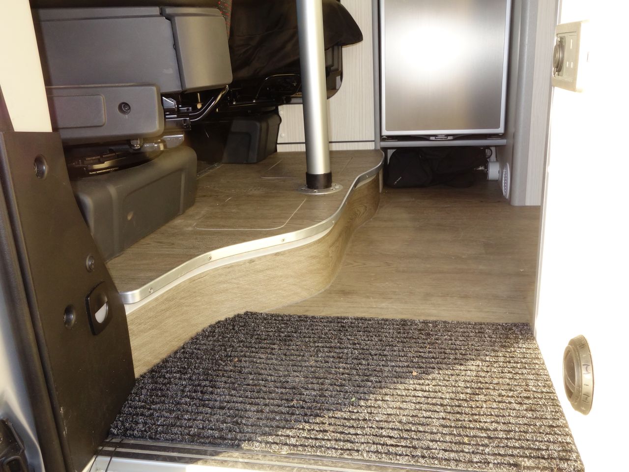
It took *ages* to find a suitable profile to trim the edge of the plinth floor. I tried bending narrow aluminium angle and u channel, with and without annealing, but only succeeded in getting kinked lengths of metal. I eventually found the ‘LA205’ profile on ebay:
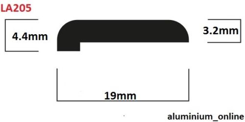
This was just about right to span the 12mm floor ply + ~4mm Altro.
I bent it to shape before screwing and gluing it to the edge of the floor.
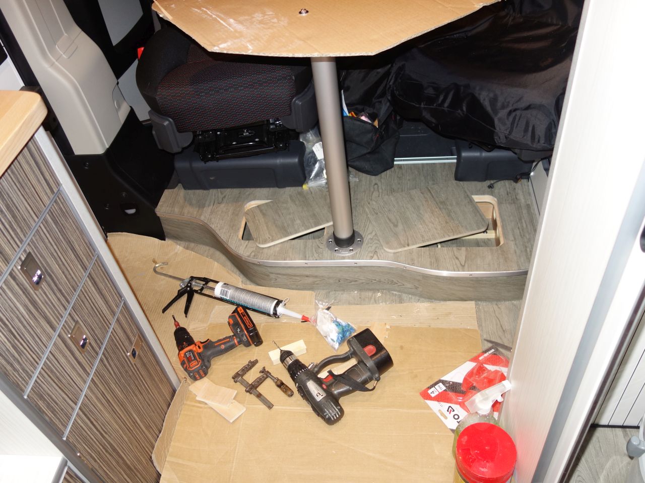
It came out OK, I think! 🙂
I eventually fitted a pair of handles with a spring loaded ring (to avoid them rattling):
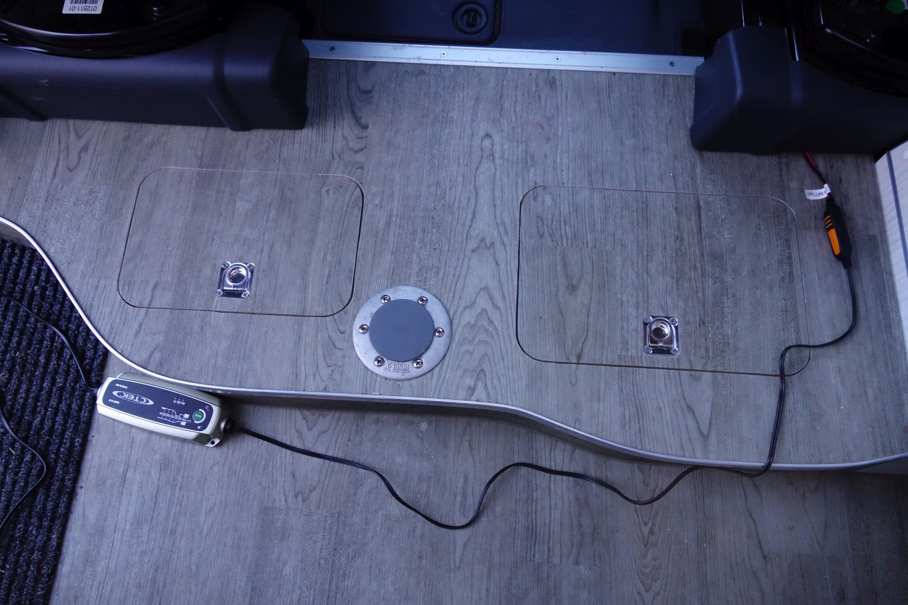
I had intended to fit magnets to hold the hatches down, but they have never moved, so I won’t bother.