
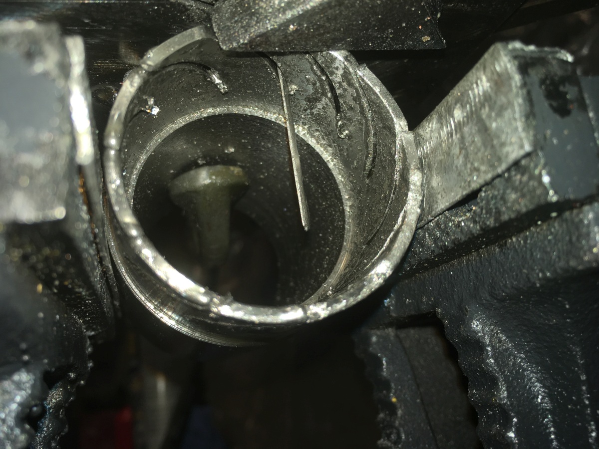
Behind the combustion chamber is the ‘nozzle / guide vane assembly’ – NGV.
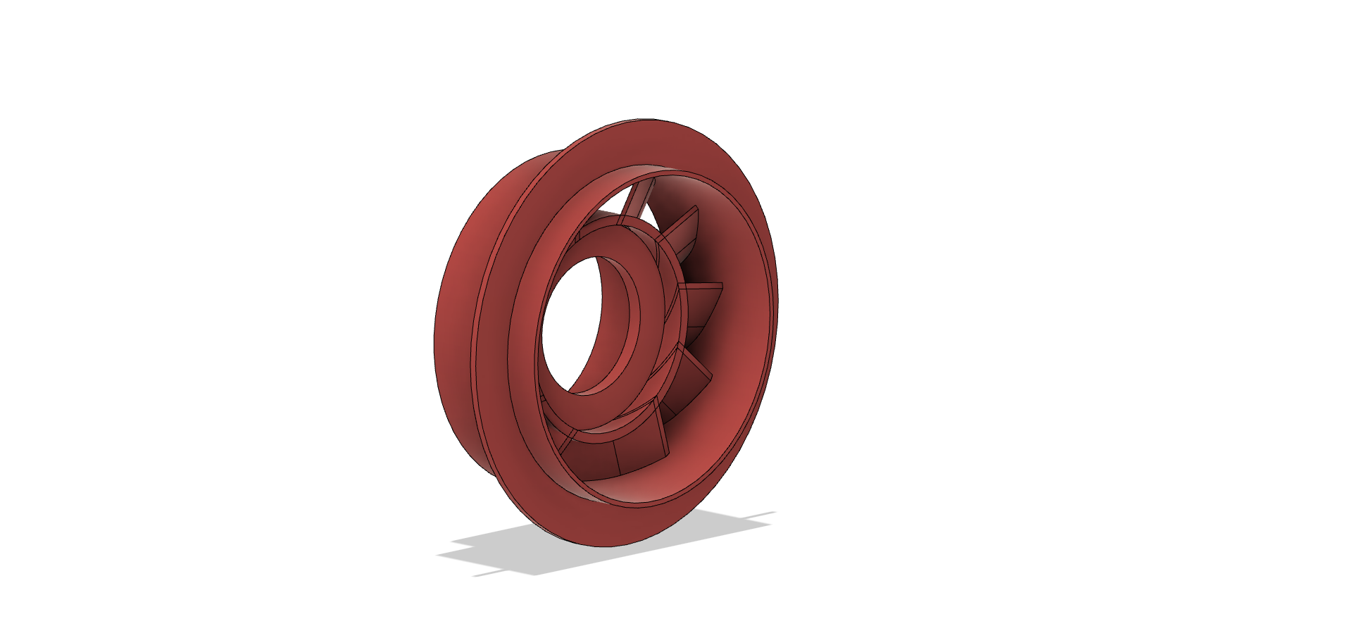
The hot gasses from the combustion chamber get funnelled through this and are sent corkscrewing into the turbine wheel. It’s made of an inner and outer ring with curved vanes slotted into them.
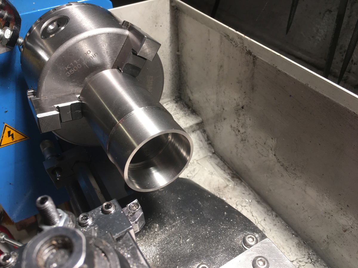
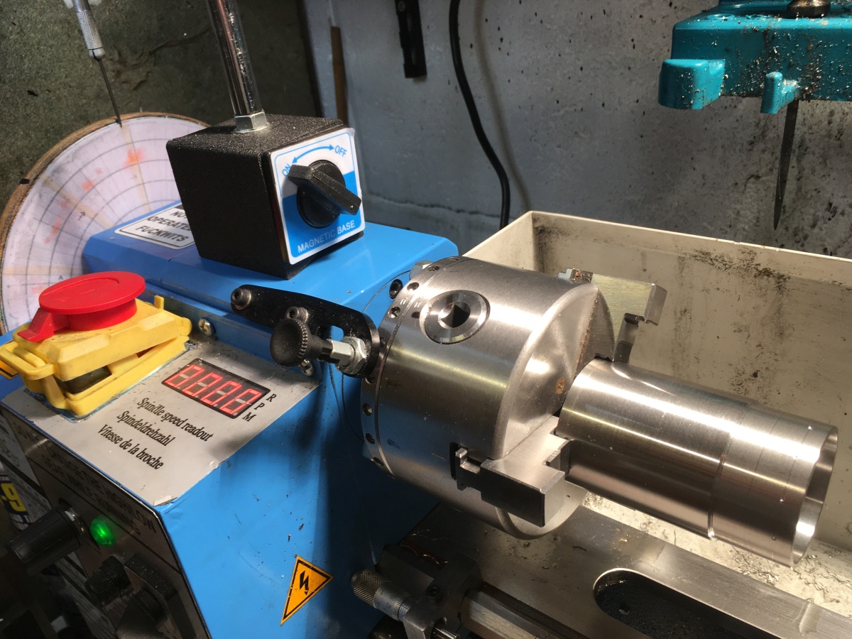
M-Machine came up trumps with some thick wall 304 stainless tube that could be machined to the right size for the inner and outer rings:
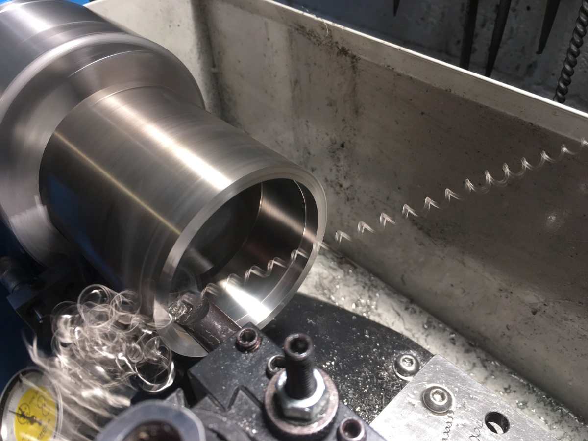
I used my ‘poor man’s dividing head* to mark a notch at each vane on the outer and a ‘pip’ at the centre of each blade slot on the inner – there are 11 of them which defeats my 24 hole index pattern.
(*just a disc on the end of the spindle with a paper pattern stuck to it and a pointer)
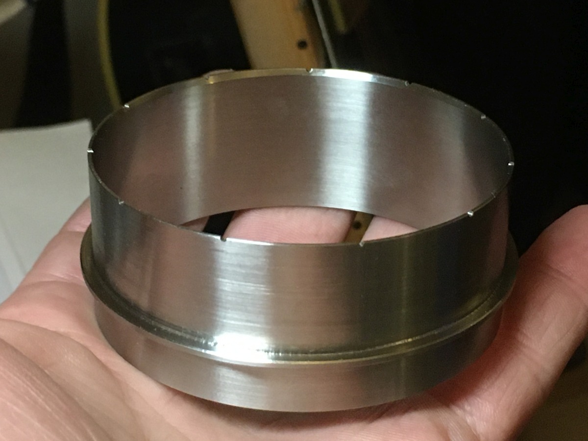
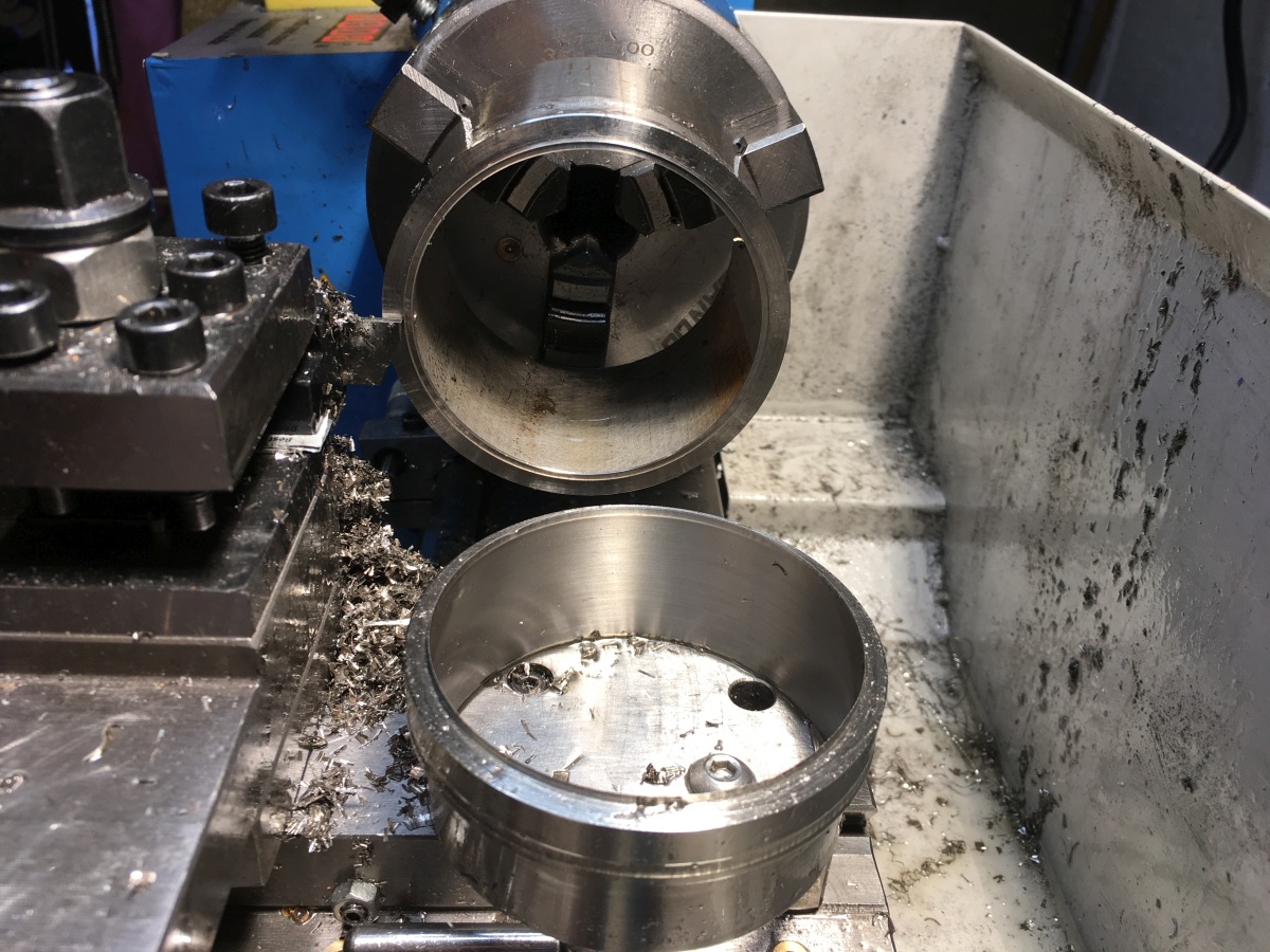
I didn’t part off the inner just yet because of the next bit:
Cutting the curved slots through the inner ring is a bit of a puzzle. They aren’t radial – they have a constant angle as the curved sheet metal vanes need to slot into them. The book suggests cutting them by hand with a ground down hacksaw blade. Eleven of them? In 2mm stainless? B*gger that for a game of soldiers!
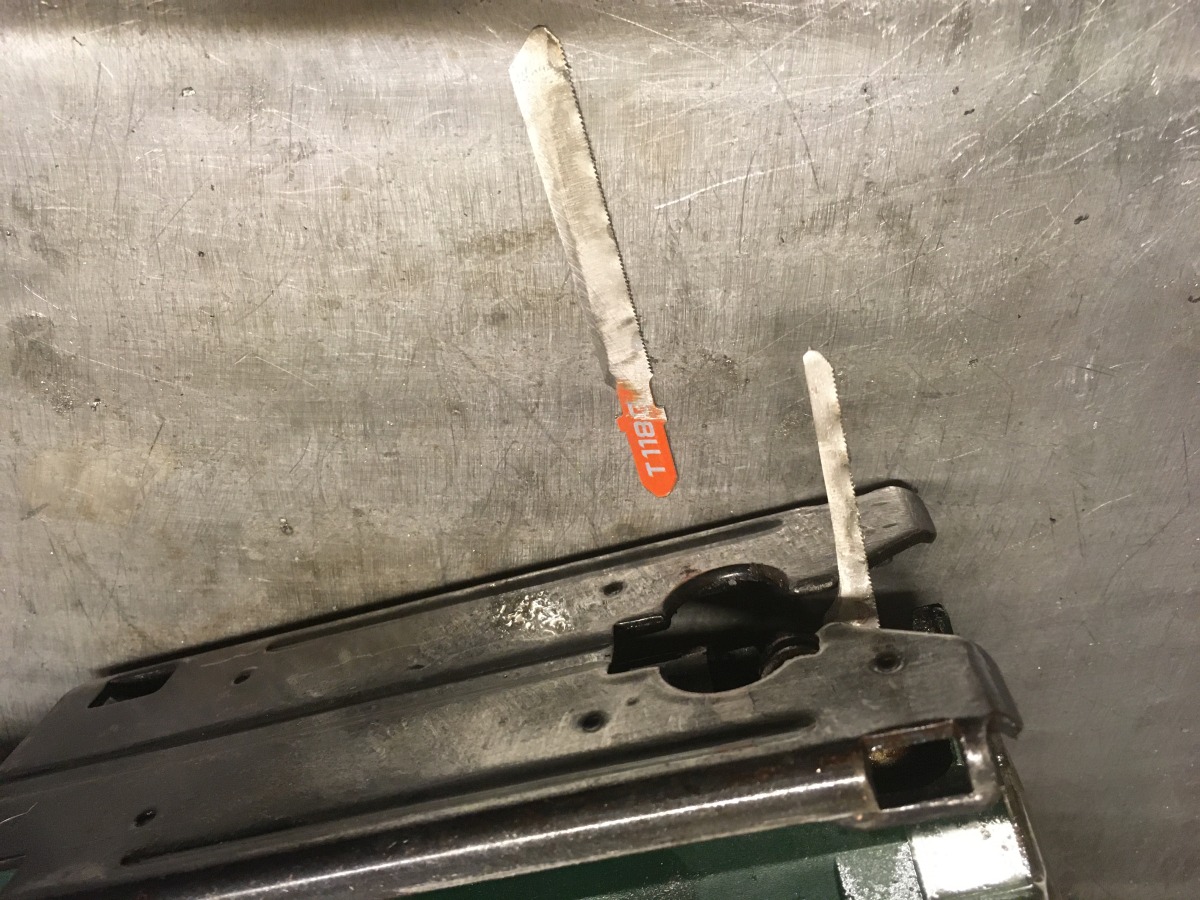
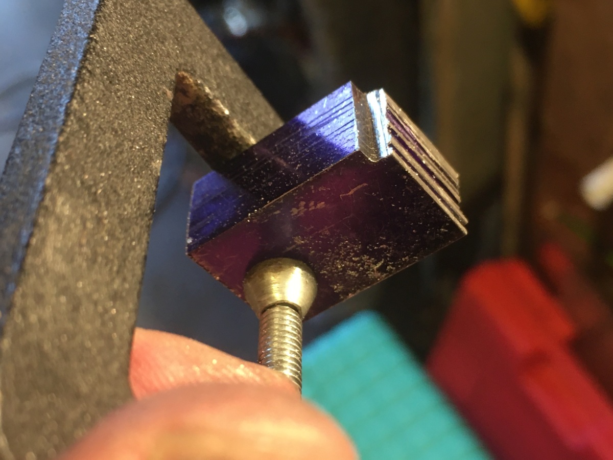
I made a plate plate that clamped to the excess stock on the part with fences and stops on it so that my jigsaw would follow the right curve while staying flat. It worked well, but was not a pleasant experience! I don’t think it helped that I had ground some of the ‘set’ out of the blade to get the slot width matched to the sheet I was using for the vanes (0.9mm thick 316 stainless steel) and had ground away the back of the blade to allow it to cut the tight curve. (Modified blade in the saw, with a standard one for comparison.)
This is the jig showing the path of the cut – the part clamps underneath against an end stop and a fence to keep it square to the plate and I spin the part around until I can see one of the ‘pips’ on the centre line marked on the jig, grit my teeth and start jigsawing.
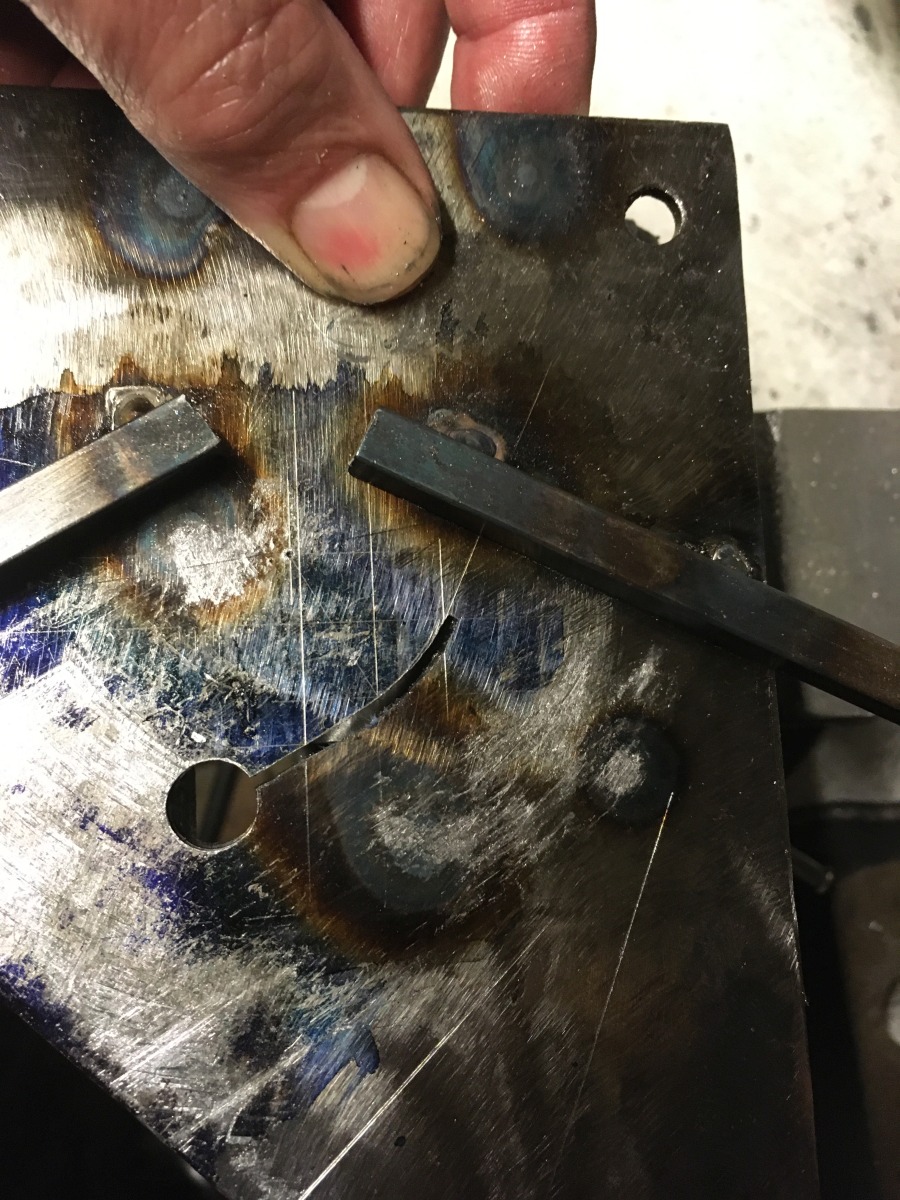
View from underneath the jig while cutting
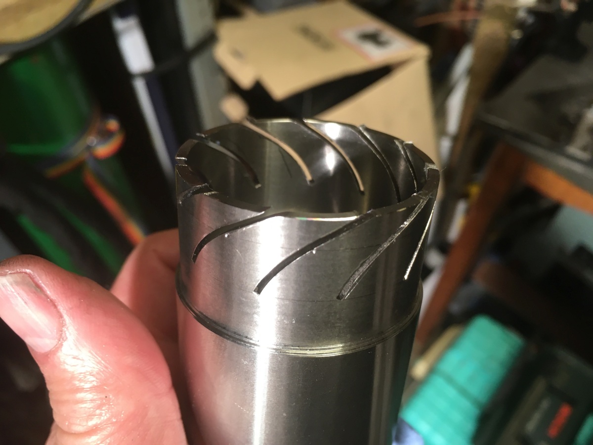
Hey, it worked! You can tell that the slots are converging towards the end of the part (forming the ‘nozzle’).
The vanes are 0.9mm 316 stainless – Inconel sheet would be better, but you’ve got to use what you can get. They were just filed to size as most of the edges will get trimmed later.
After bending the curve into them, they were slotted into the inner and tack welded.
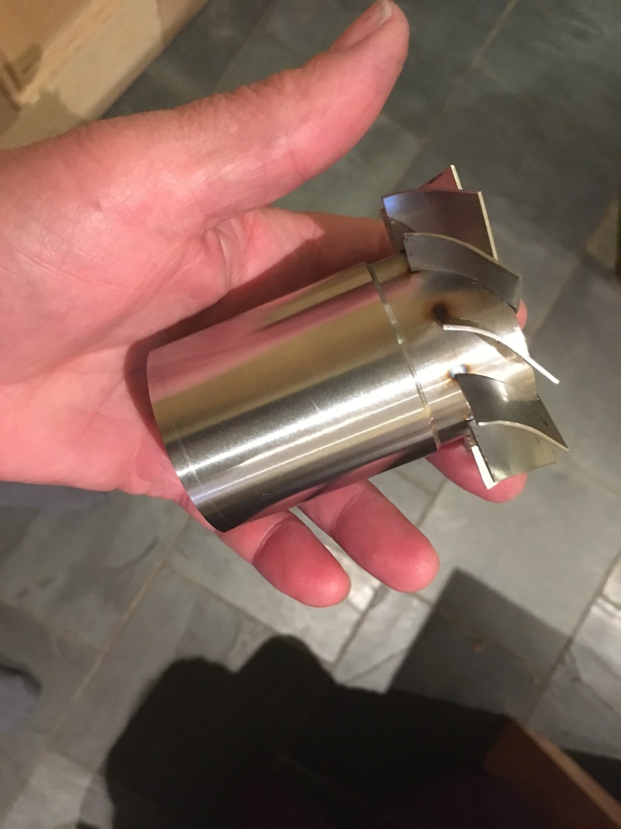
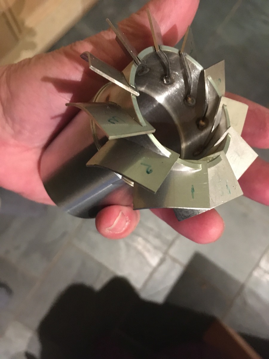
I was then stumped as to how to go about protecting the rear surface from ‘sugaring1‘ when fully welding it.
I thought I might need to make / buy a purge box so that the whole part could be surrounded by argon when welding, but got a much better suggestion from the Mig Welding Forum.
1 ‘Sugaring’ is the colloquial name for a distinctive, ugly, form of oxidation that occurs due to ineffective shielding during welding of stainless steel.