
Before I could put it together, there were a few odd jobs to do:
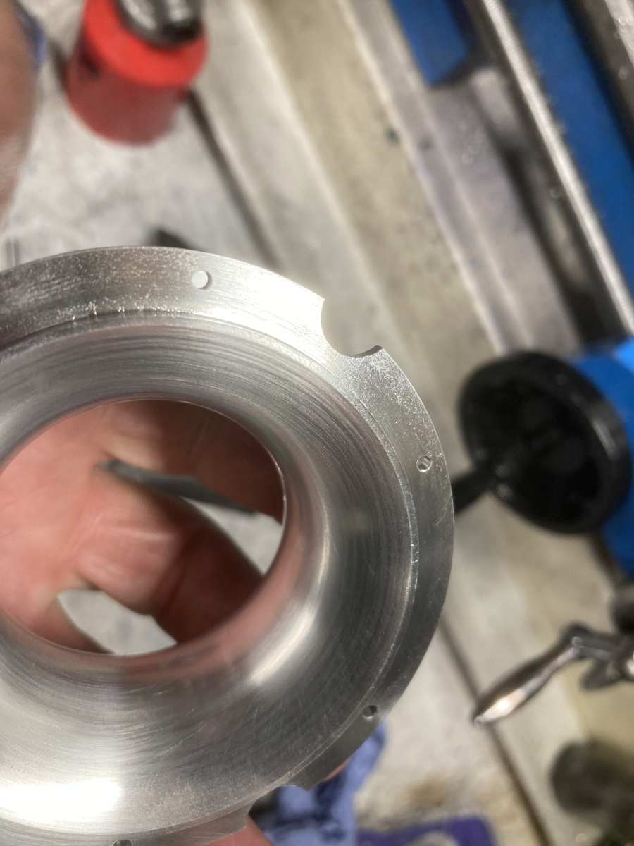
I needed to increase the size of the cut-outs in the intake that are supposed to clear the diffuser securing studs – I had made cut-outs already, and they cleared the studs, but they weren’t big enough to also clear the nuts! (Best laid plans, etc. … )
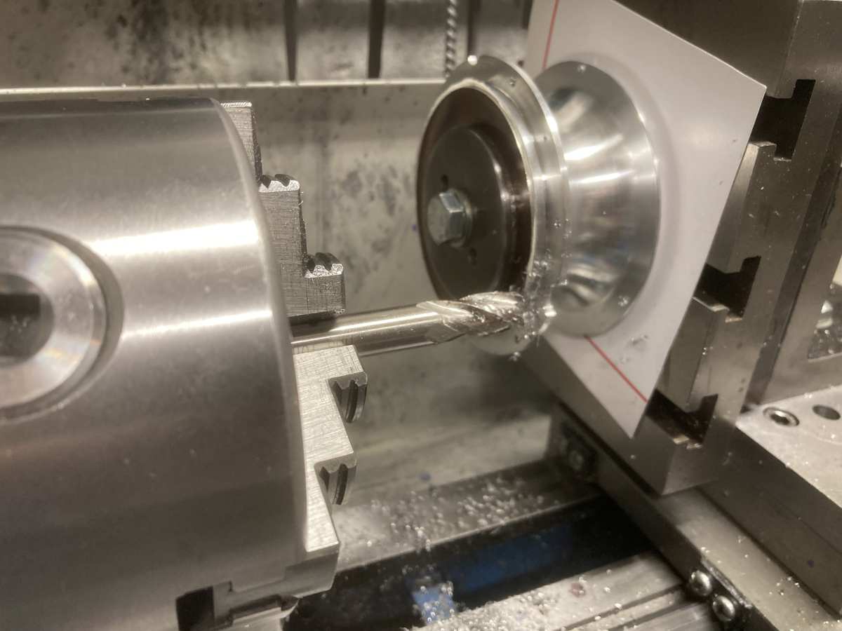
I just plunged through it with a 10mm end mill (I know, I know: I shouldn’t hold end mills in the chuck, but it was a plunge cut and the chuck was nice’n’tight).
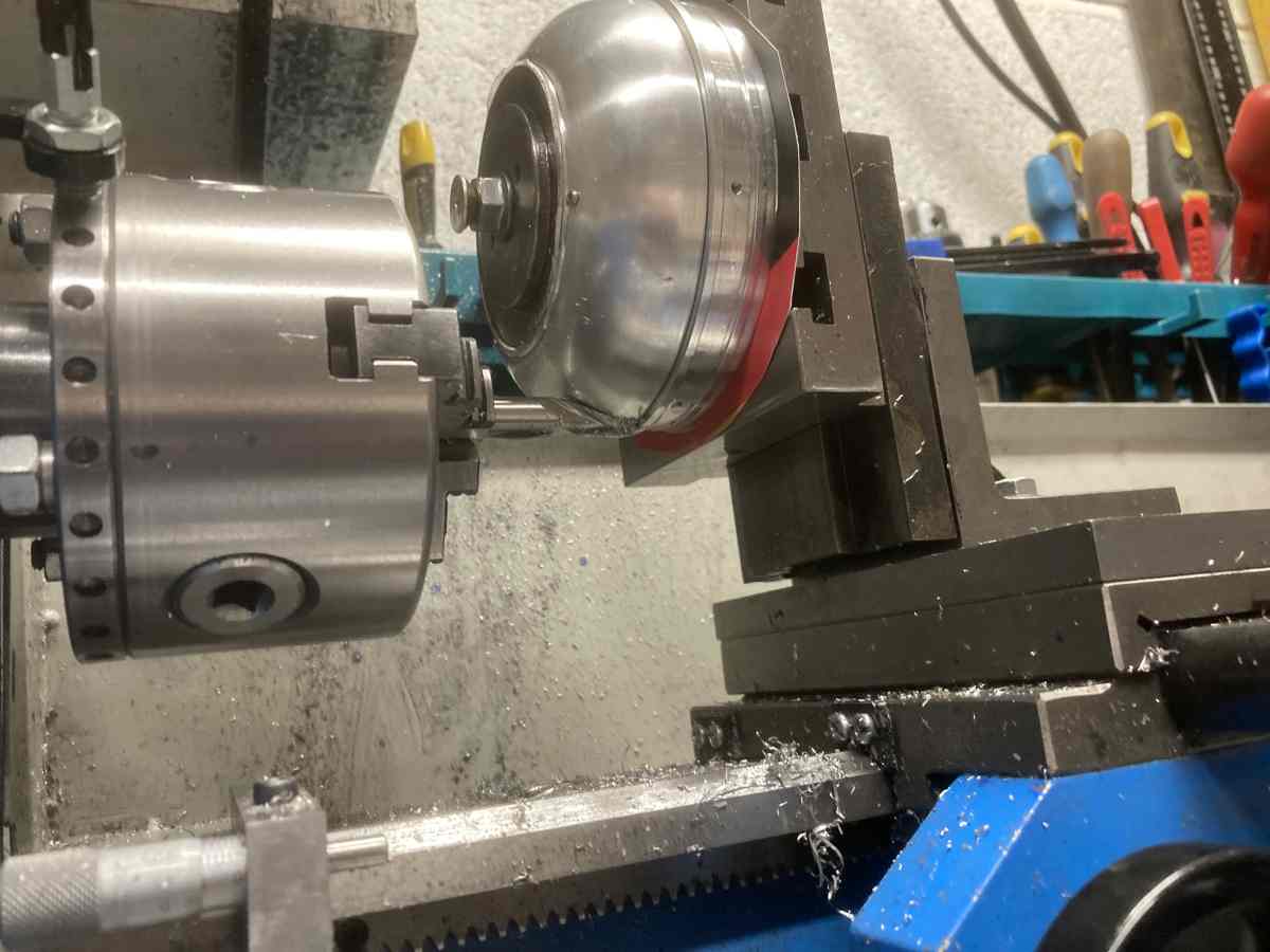
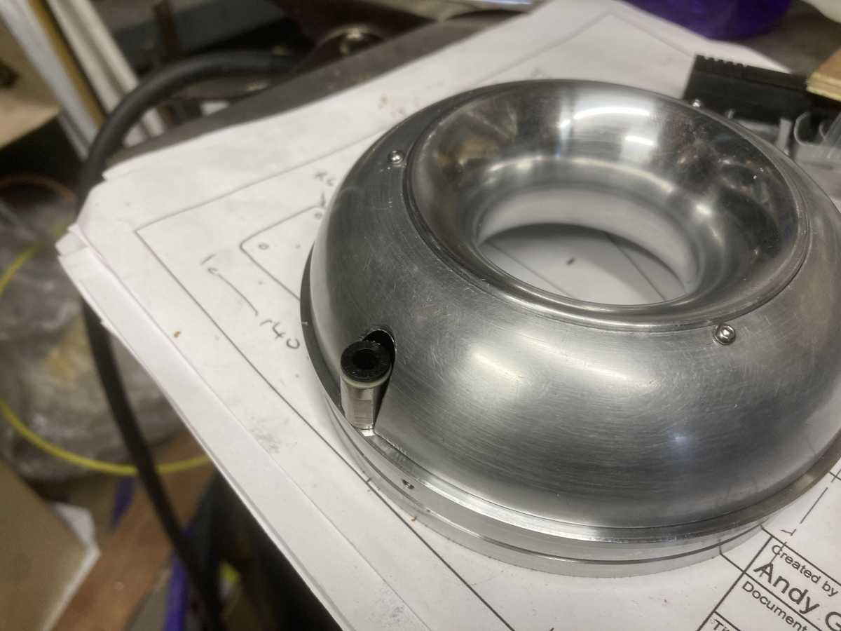
While I had the vertical slide set up on the lathe, I could also drill and tap for the lubricating oil fitting and cut out the front fairing to clear it – I had wanted to bring the oil pipe out inside the fairing and hide the flow restrictor in there, but I couldn’t figure a sensible way of doing this, so just brought the oil pipe through the very edge of the diffuser as per the book.
Scalloping out the fairing was a bit twitchy as the metal was very soft and gummy, having been annealed before spinning, and I was relying on the three small mounting screws to secure it. All went OK though.
The compressor intake clearance didn’t close up any when the assembly was bolted together, so I also made up new front spacer that was 0.15mm thicker than the previous one.
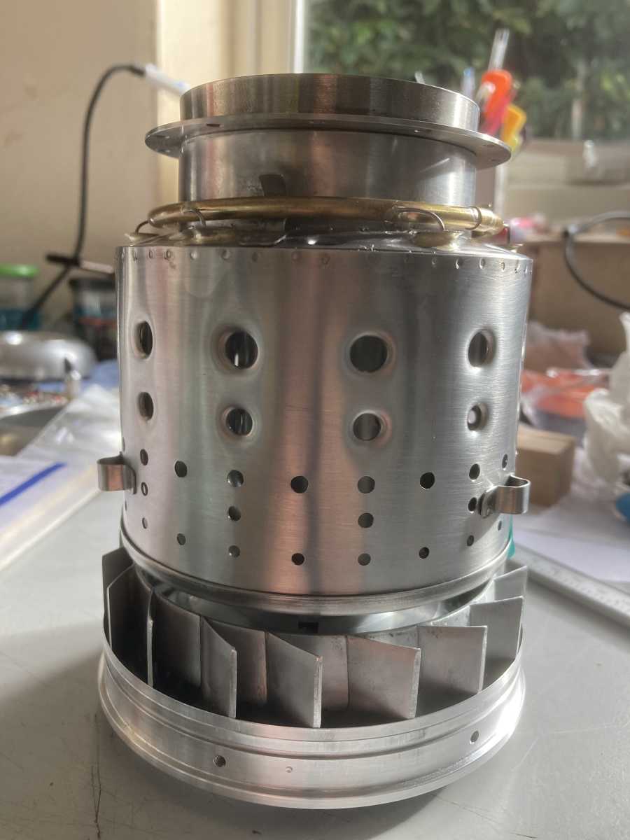
Then it was time for a trial assembly! (Without the combustion chamber for now):
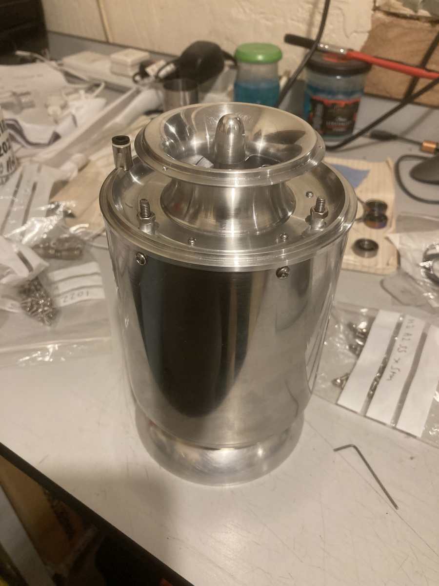
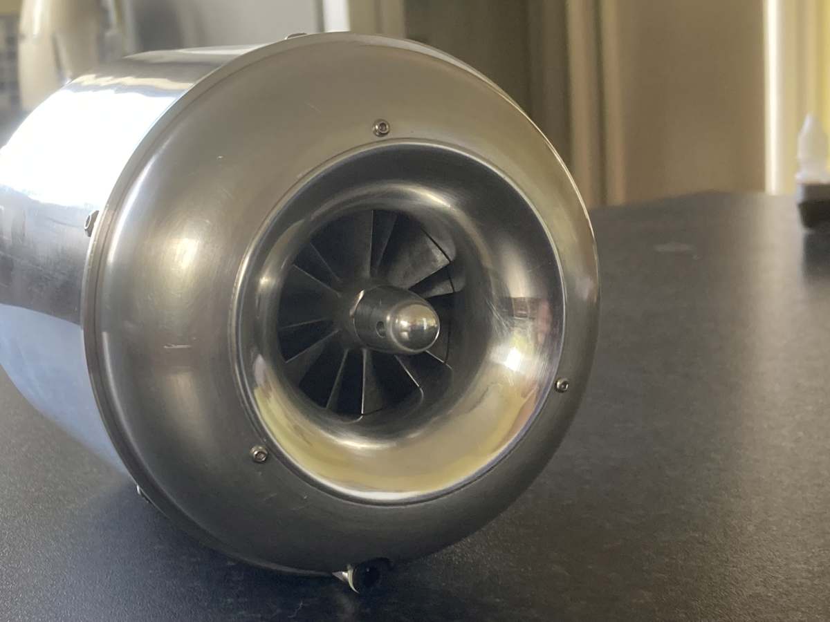
I was very pleased with the way it went together – everything seemed to fit, and the rotor even spins round!
Getting the clearances around the compressor and (especially) the turbine wheels is important to get the engine running well (or at all, even). The new front spacer has brought the compressor clearance to just less than 3 layers of tape (somewhere between 0.15mm and 0.23 mm – probably nearer the 0.23mm) which I’m reasonably happy with, and the compressor wheel looks level with the diffuser body (I’m blaming the difference on my decision to change to a different set of bearings to the ones I originally installed when I set the level of the compressor wheel…)
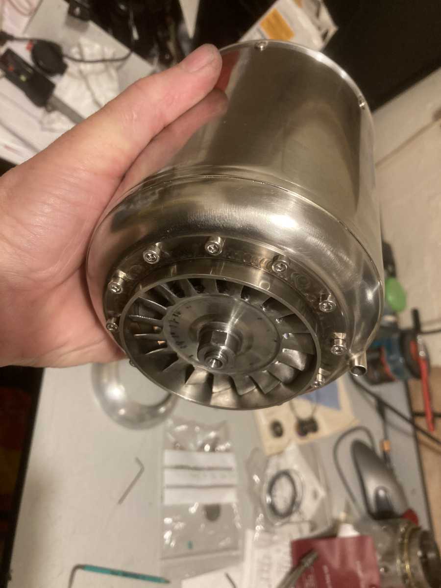
The turbine disc isn’t quite central in the NGV – it is spinning true, but the clearance is 0.13mm on one side and 0.23mm on the other (so something has gone awry by 0.05mm somewhere, but overall, I think it’s gone OK. I fully expect the whole thing to move a bit when it gets hot, and I may need to skim the turbine wheel or NGV if it rubs when running.
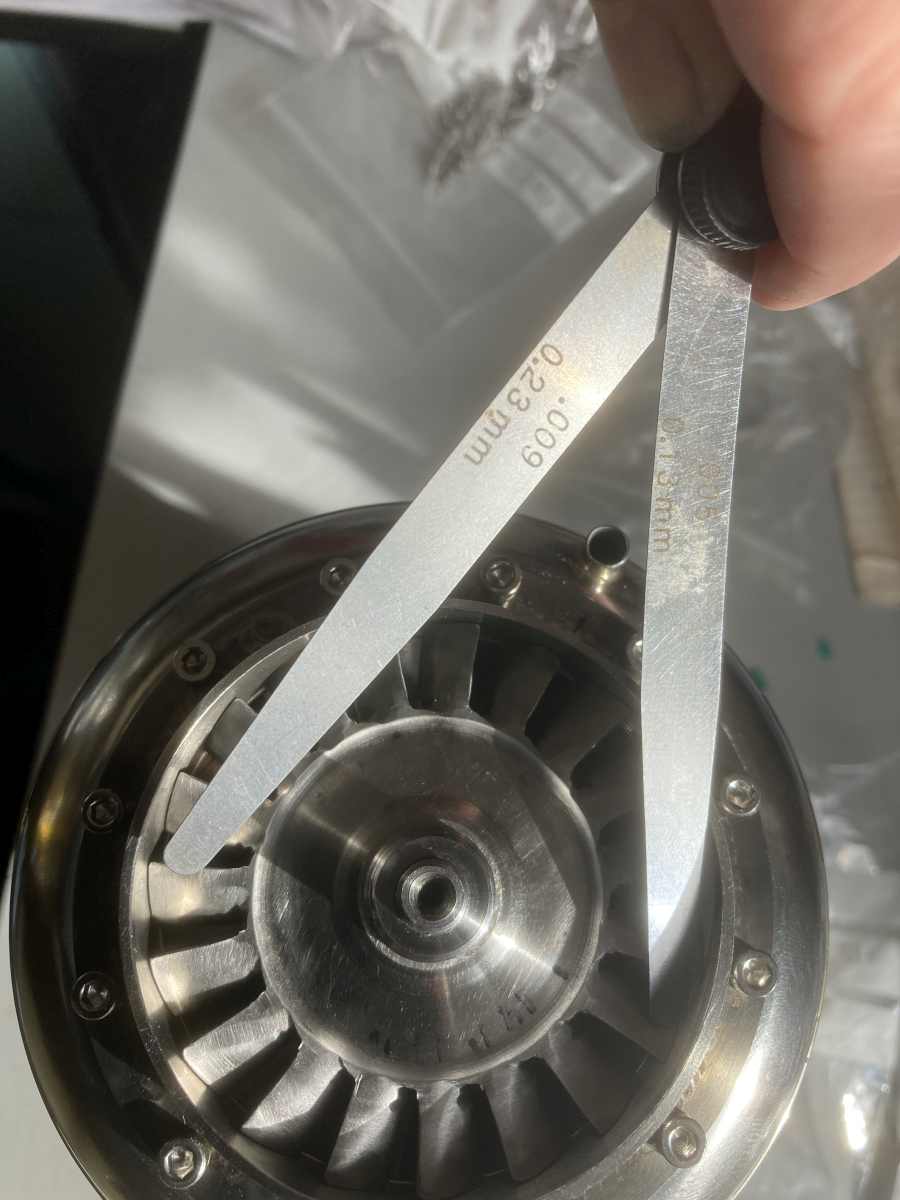
(The feeler gauges are photographed where I could see their thickness – they were stuck down the gap at the tips of the blades to check the clearance!)
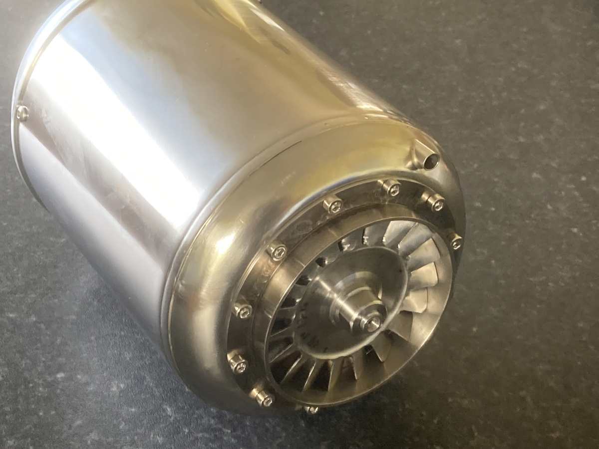
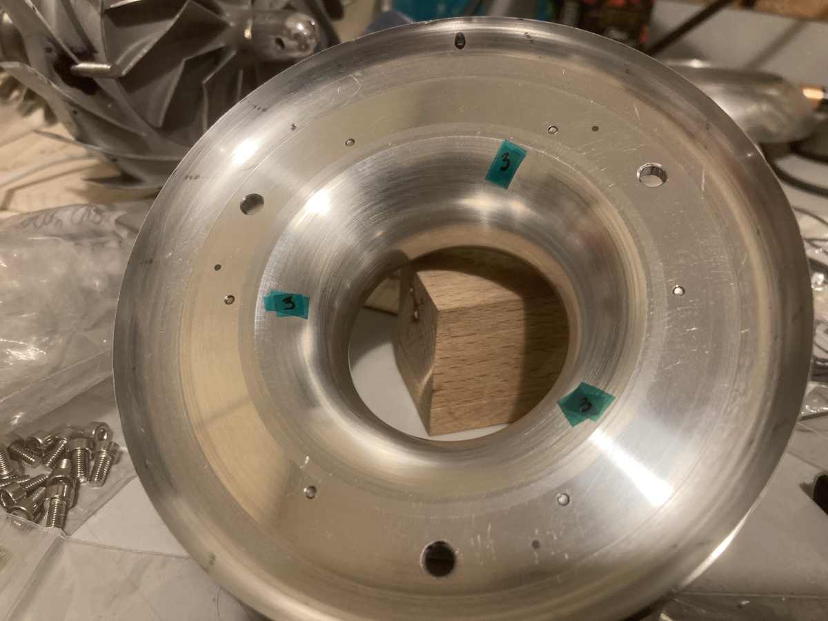
With the parts assembled, I could measure where the NGV sits on the shaft tunnel – the actual position depends on the tolerance stack-up from five separate parts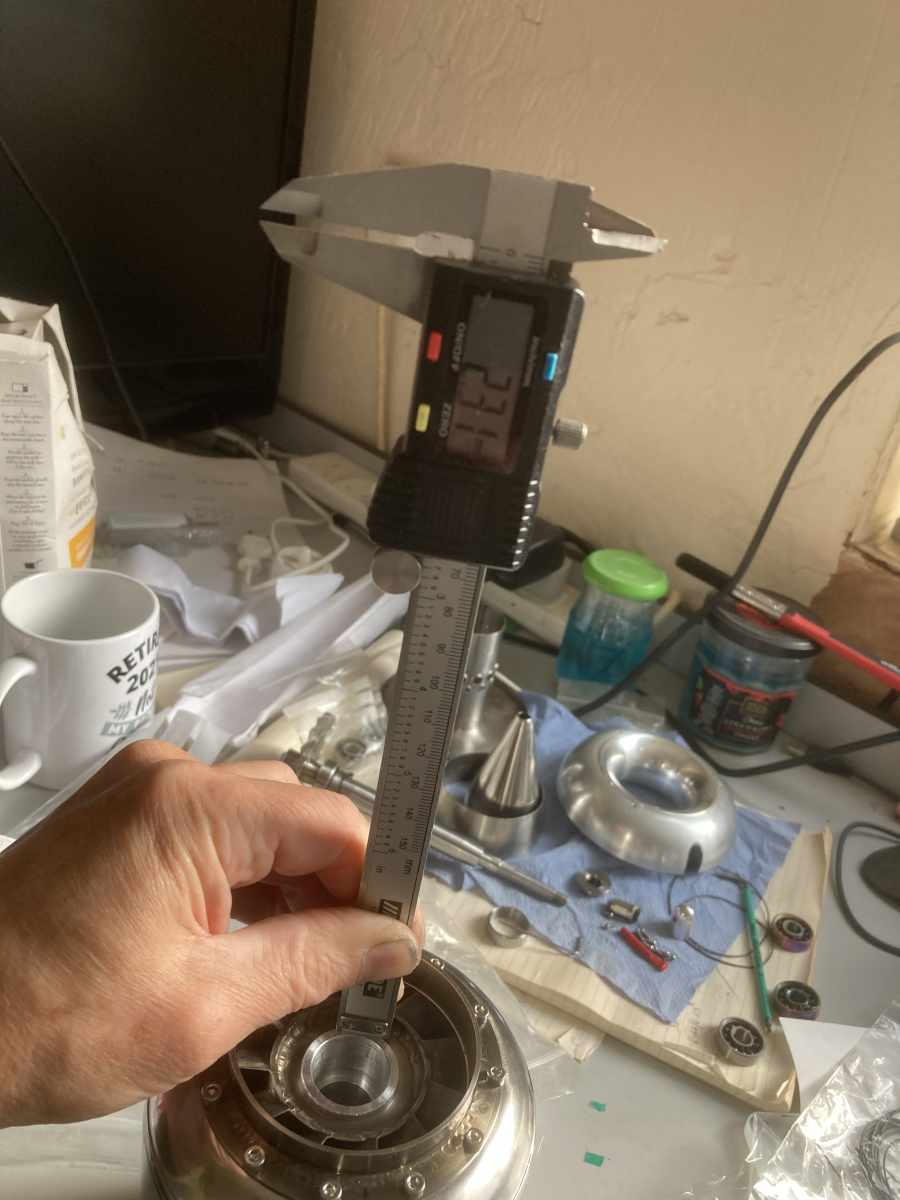
When I took the engine apart again, I could then use this measurement to double check the clearance between the front of the combustion chamber and the back edge of the diffuser. I did this before finally fitting the front of the combustion chamber in case I needed to shorten it. (I did shorten the ‘tail pipe’ on the combustion chamber by ~1.5mm – I think the various angles and tolerances in my work had stacked up to make it a bit longer than intended.)
There’s about 6mm clearance between the combustion chamber and diffuser, which I think is plenty for air to be able to flow to the holes in the combustion chamber inner. (I think it needs a minimum of 3 or 4 mm to match the area of the air holes in the inner wall.)