
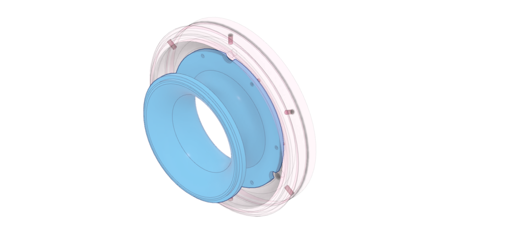
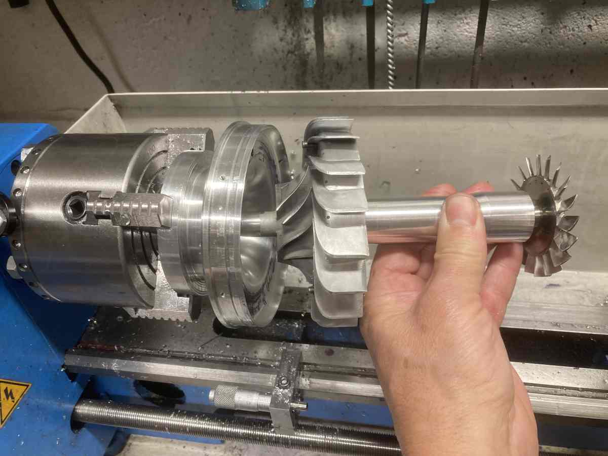
I prepared the intake blank in a similar way to the diffuser cover and hogged out enough material that I could bolt the diffuser cover to it in the lathe so that they could both be turned together.
The intake needs to be machined to match the curved profile swept out by the blades on the compressor wheel. The depth of it needs to be just right so that the profile merges into the face of the diffuser cover. It’s important to get a reasonably close and consistent clearance for the compressor wheel to work properly.
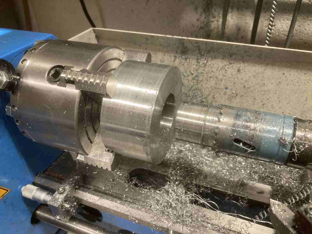
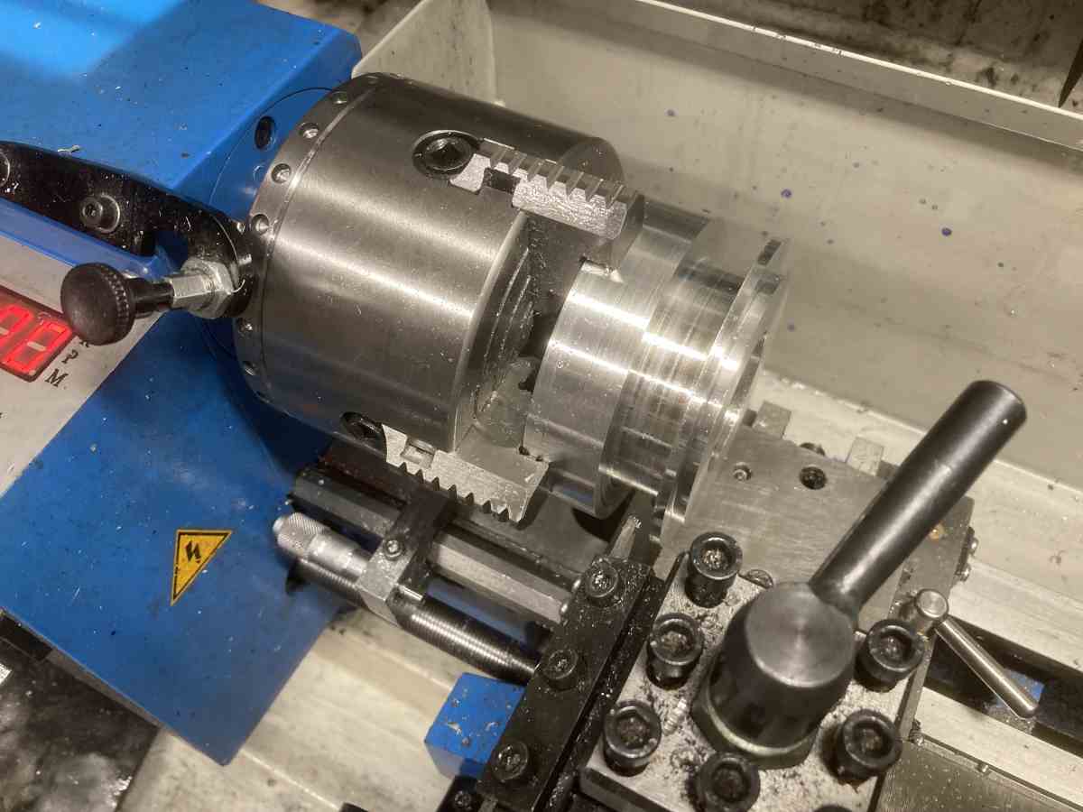
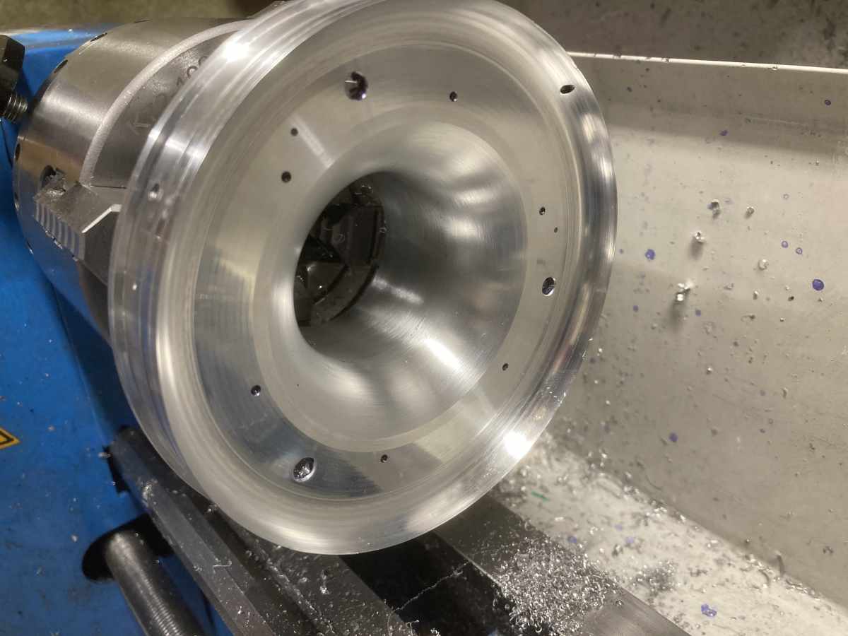
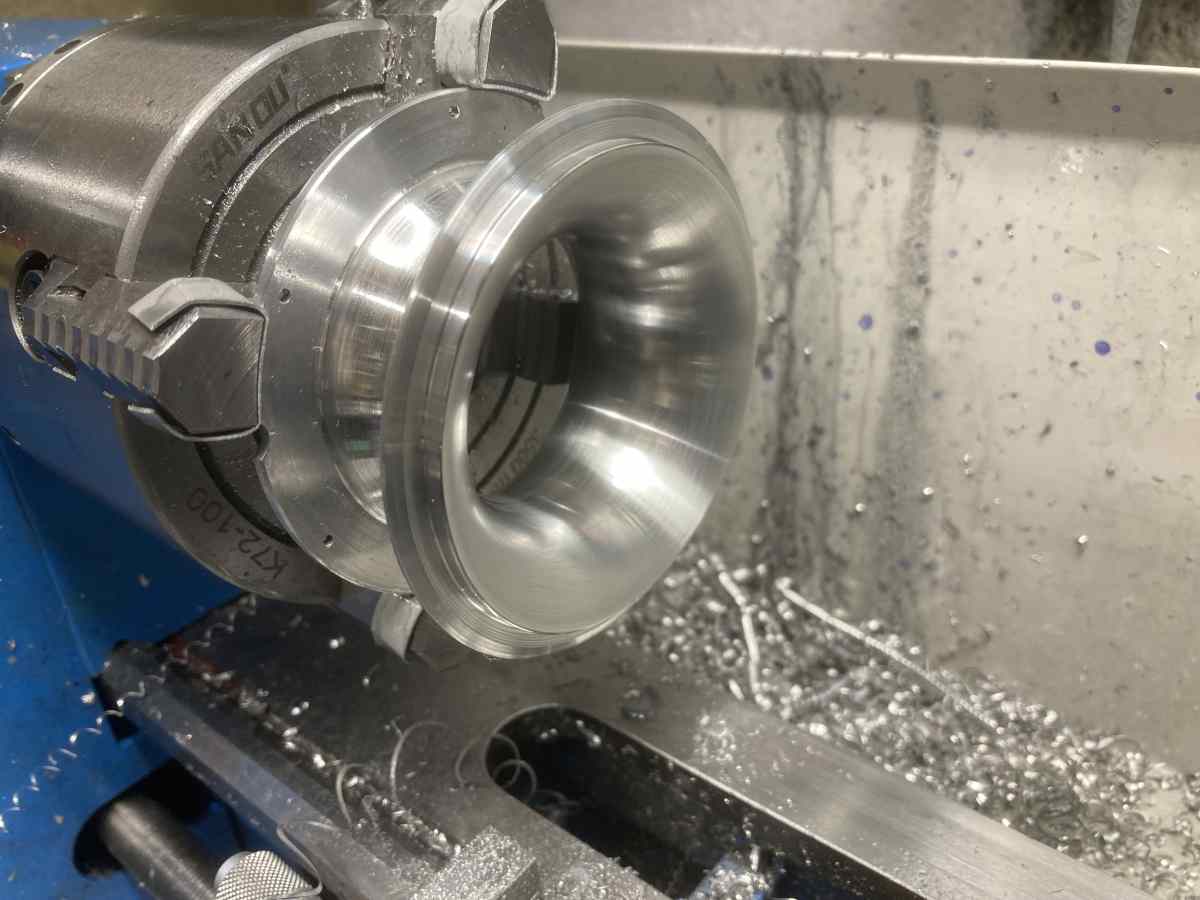
With the inlet faced off level with the diffuser cover and the through hole bored to the finished size of the narrowest section, it’s ready for a mammoth session of turning by numbers…
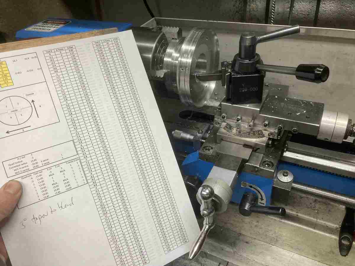
I find it easiest to set the top slide parallel to the bed and use this for the Z feed, rather than the carriage. I set a stop on the lathe bed where the tool just touches the face of the part and zero the top slide dial. Cross slide dial is zeroed by touching off on the bore. I can then wind the carriage back, increment the cross slide and set the desired Z travel on the top slide without cutting any metal whilst making the adjustment.
I use an excel spreadsheet to calculate how far the tool needs to be fed in the ‘Z’ direction (towards the spindle) for increments in the cross-slide (X) direction, taking into account the desired finished radius and the radius of the tool being used. It converts these dimensions into the number of complete turns of the handwheel and the dial reading. (Vital for me, as my cross slide pitch is 1.25mm, so for consistent 0.2mm increments, I need to stop variously on the odd number graduations, the even number graduations or the ‘5s’ between them!)
For an internal curve like the inlet, the first Z value will be high, and gradually reduce as the cross slide is wound out (decreasing X).
For each X value, I set the Z value on the top slide (off the work) then traverse the carriage up to the stop (using auto feed if needed) to cut to the Z depth specified, back the carriage off again, wind the X out 0.2mm and repeat. There’s no need to reset the top slide to zero every time unless you lose track of where you are (but obviously the reading must be approached from a consistent direction to eliminate backlash – I make a sharpie mark on both slides at the zero position in case I get lost).
I’ve found machining this way to be quite straightforward as long as I work methodically (e.g. crossing out each setting after it was cut) and not too tedious. Trying to cut in the other direction (Constant Z increments and variable X) is much more nerve-wracking as the lathe will be cutting whilst the X values are being dialled in so a steady feed rate and no overshoot are important for critical curves. It is also necessary to wind the X slide in and out the full distance every time.
The book specified a 16.7mm radius curve for the inlet which I think was meant to give 0.3mm blade tip clearance on a wheel with a 17mm profile radius. I though I could do a little better than that, and to err on the side of safety, I went for 16.85mm radius which should have given ~0.15mm tip clearance (it could always be made bigger!).
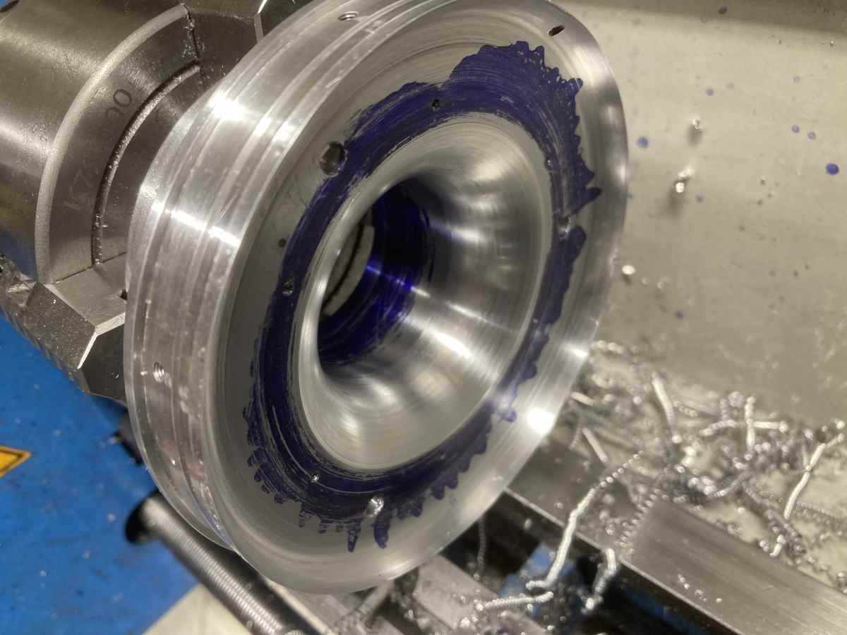
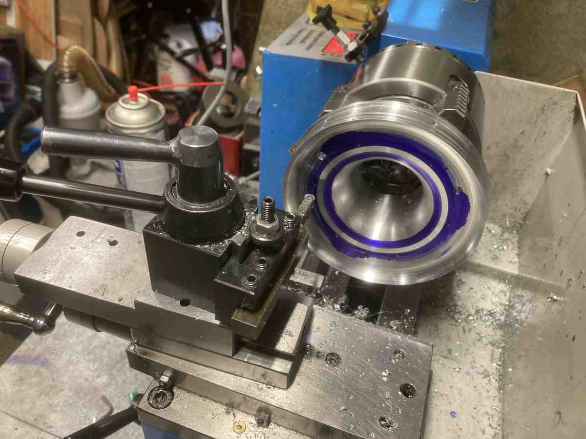
This seemed to go well, but when I tried the compressor wheel in the hole, it wouldn’t sit all the way down – there was a gap of about 0.3mm at the tips of the exducer.
Some sharpie pen and a wiggle showed that the problem was that the radius machined in the cover was tighter than the one on the the wheel:
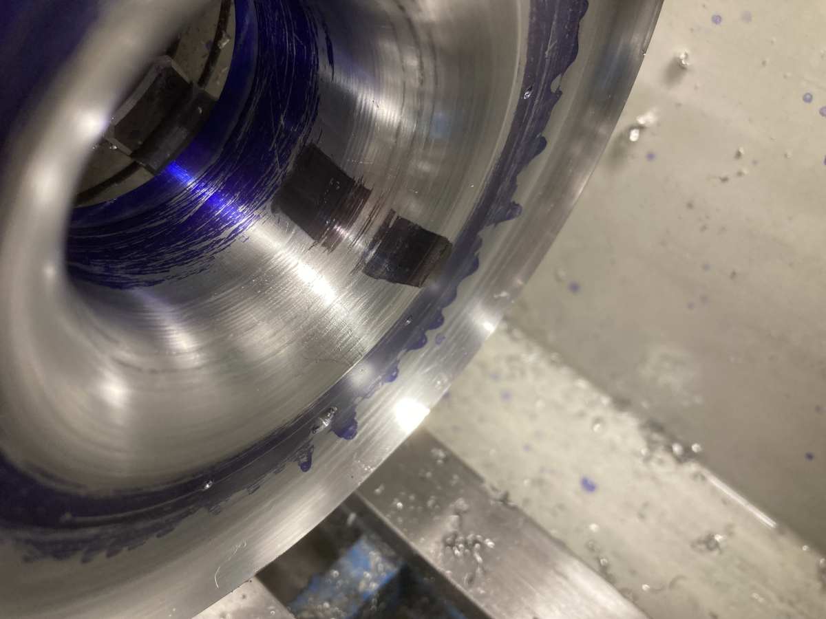
I had tried to establish the profile radius of my wheel, but it’s not easy to measure because the blades are swept back so far and I couldn’t find any drawing specifically for this wheel. There is some ambiguity as the 5326-123-2018 compressor wheel was seemingly superseded by the 5326-123-2037 for which I have seen a drawing giving an 18mm radius. I had tried to verify which it was by eye, and had convinced myself it was 17mm. Looks like I was wrong! A bit of checking on CAD verified that the 0.3mm gap was also consistent with a 18mm radius profile against a 16.85mm radius cover.
Anyway, re-cutting to 17.85 mm radius (for an 0.15mm clearance from an 18mm radius curve) was straightforward, and the wheel now fitted as expected (with the exducer tips able to go tight against the cover).
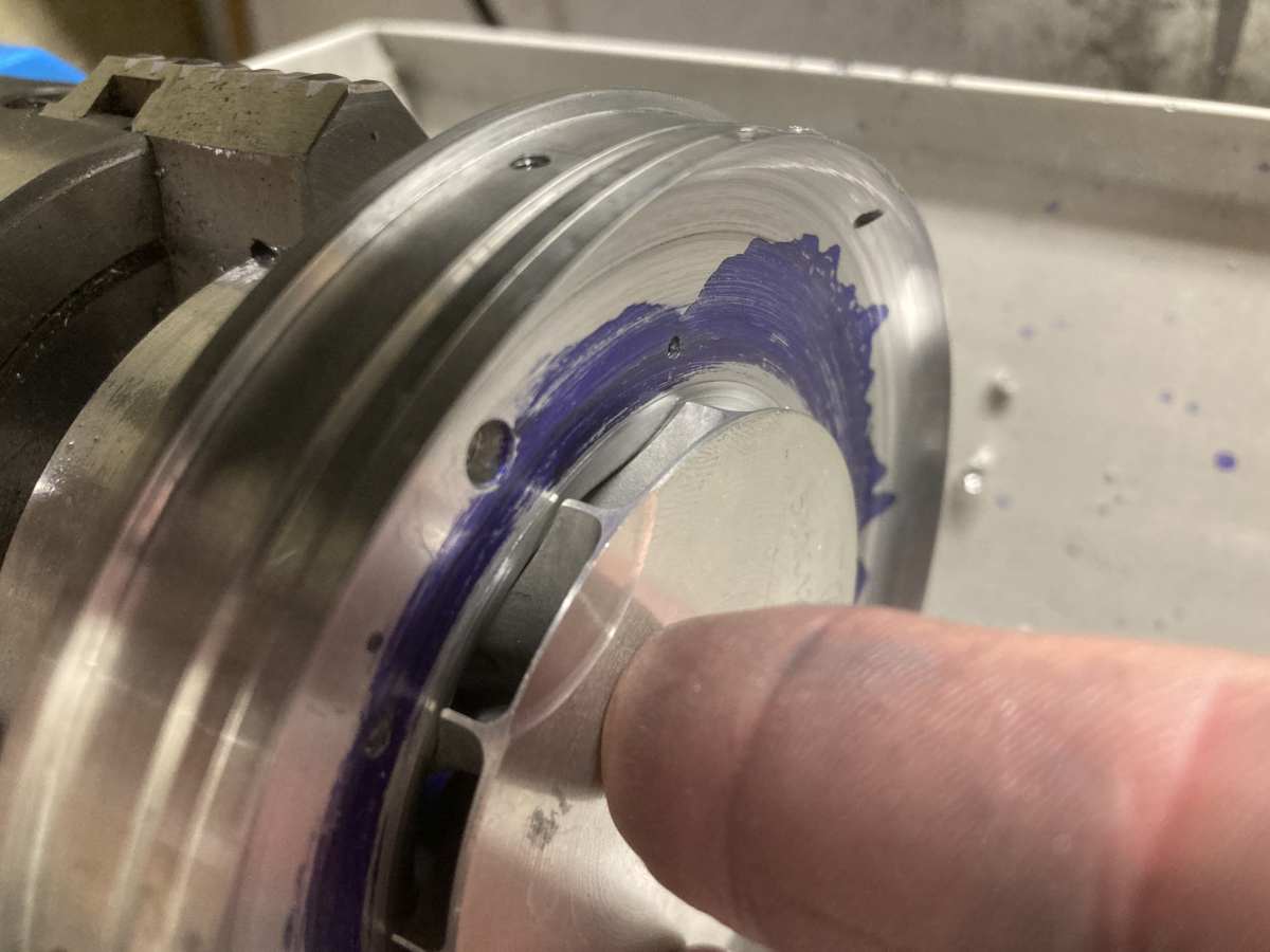
Before I disturbed anything, I wanted to make a check on the clearances in case I needed to cut the intake any deeper.
I stuck small pieces of mylar tape on the intake, in multiple layers, and offered up the compressor / diffuser assembly to see if it would still turn freely.
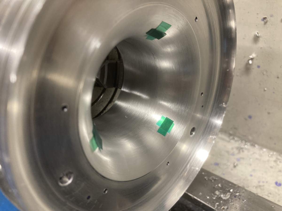
It turned out that the clearance was somewhere between 0.3mm (4 layers) and 0.375mm (5 layers) which was a bit more than I was hoping for. I knew that the diffuser vane height was accurate, and although it wasn’t clamped down, the diffuser vanes seemed to be seating against the cover; the turning by numbers had ended up exactly where it should have done, with the last few cuts doing little more than scraping the layout fluid off the surface, so unless it pulls up a bit tighter when I can get the cover securing screws in, it is likely that the wheel is a little low in the diffuser.
In any case, I decided I didn’t need to adjust the intake.
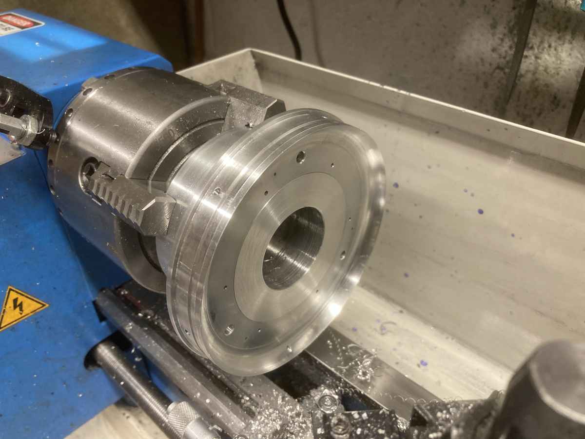
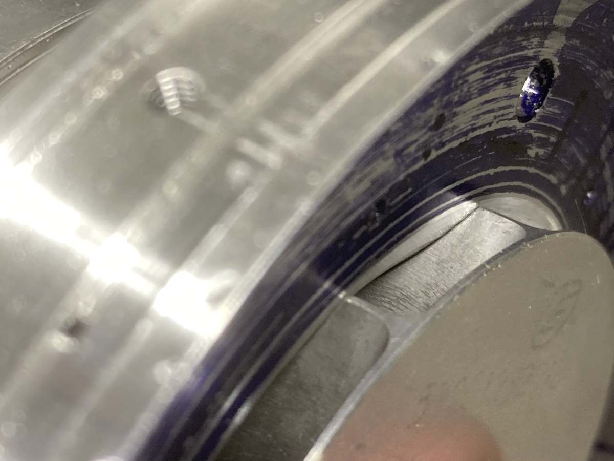
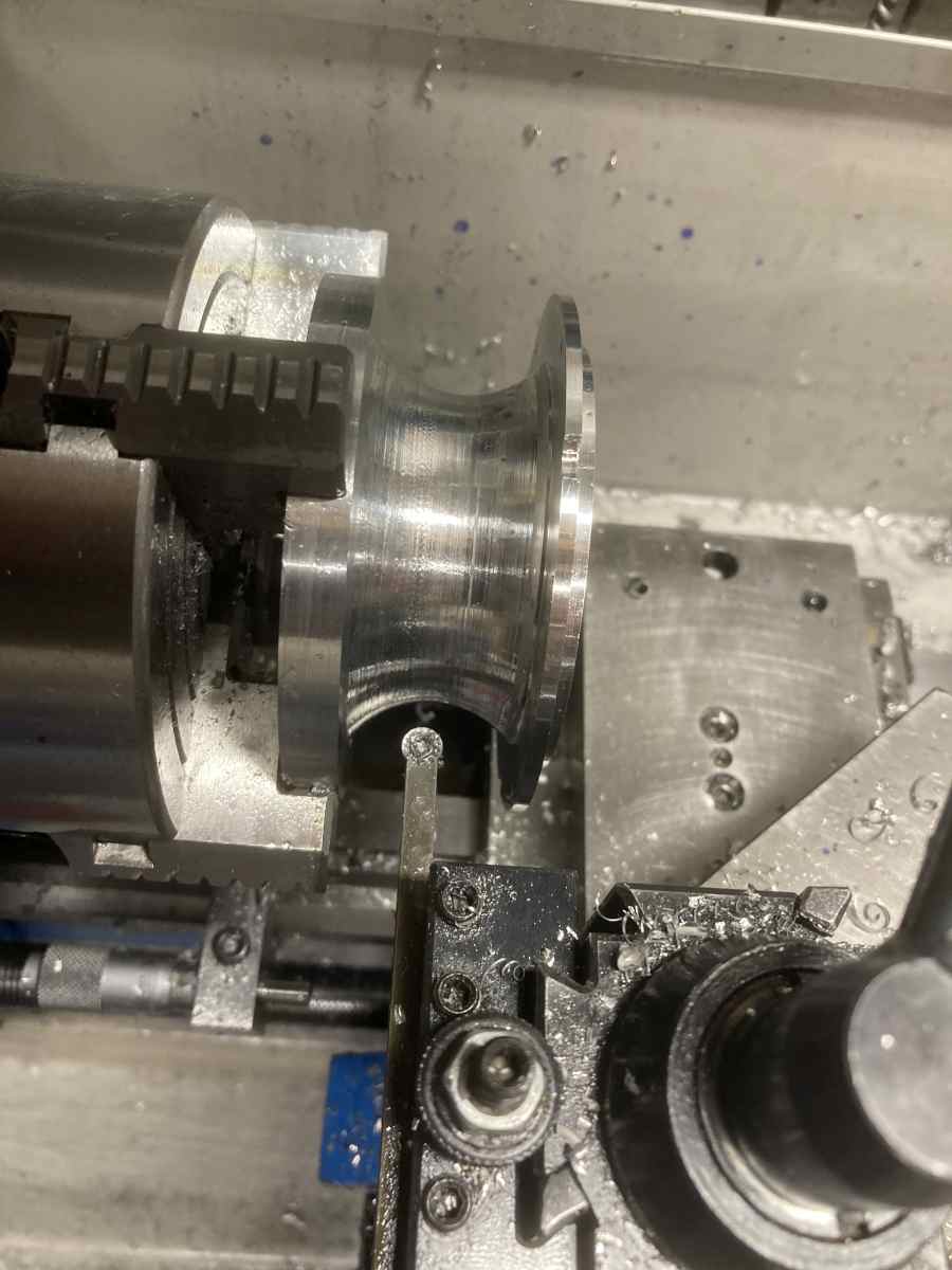
It was finished it off by machining the short, 3° tapered, section between the edge of the wheel and the diffuser vanes that blended the intake nozzle into the diffuser cover.
You can’t see the join between the two pieces – it’s about half way along the tapered section.
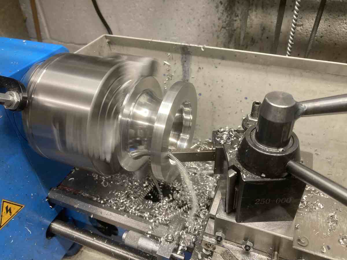
I could have just left the outside of the intake as it was (I’m not trying to get the weight down, etc.), but decided to turn it to an aesthetically pleasing curve…
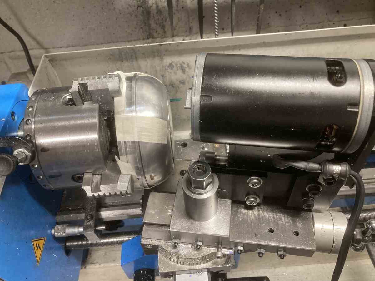
It was then flipped around so that the intake bell mouth could be machined in the same way. A 20mm radius was about right (more ‘turning by numbers).
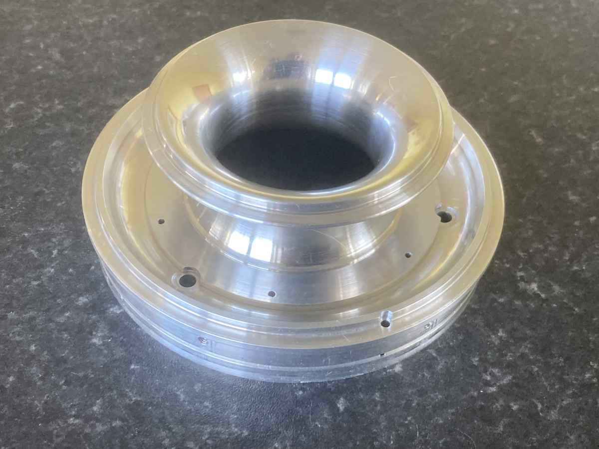
The front of the intake was machined away to leave a flange to take the fairing. The angle was arrived at by trail and error.
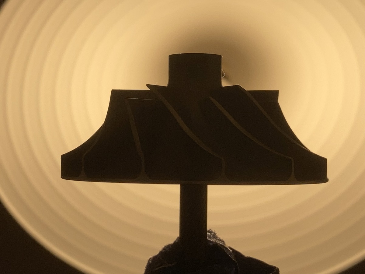
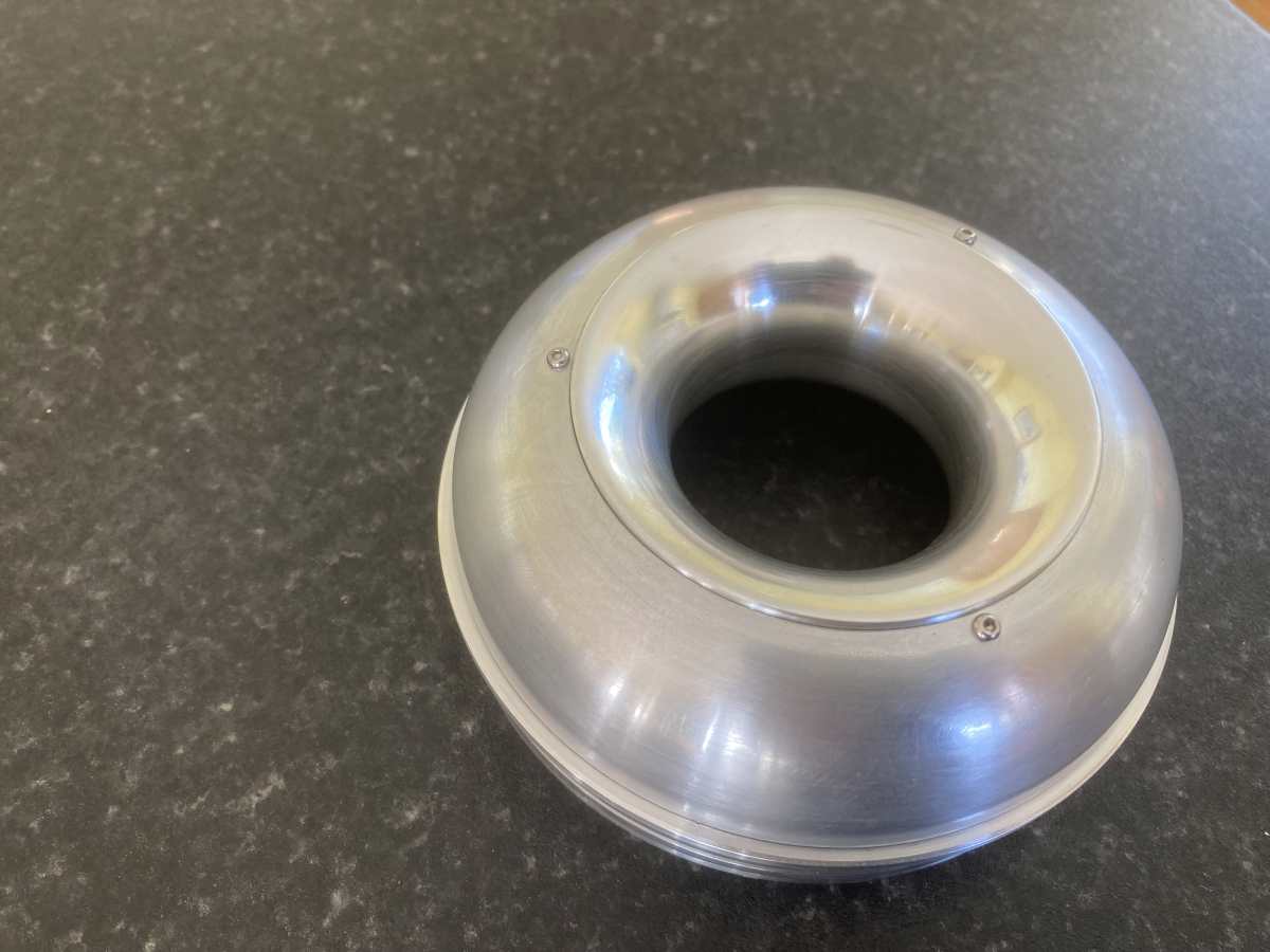
The finished item – I tried not to polish it (because a slightly rough surface is supposed to flow better), but it ended up shiny anyway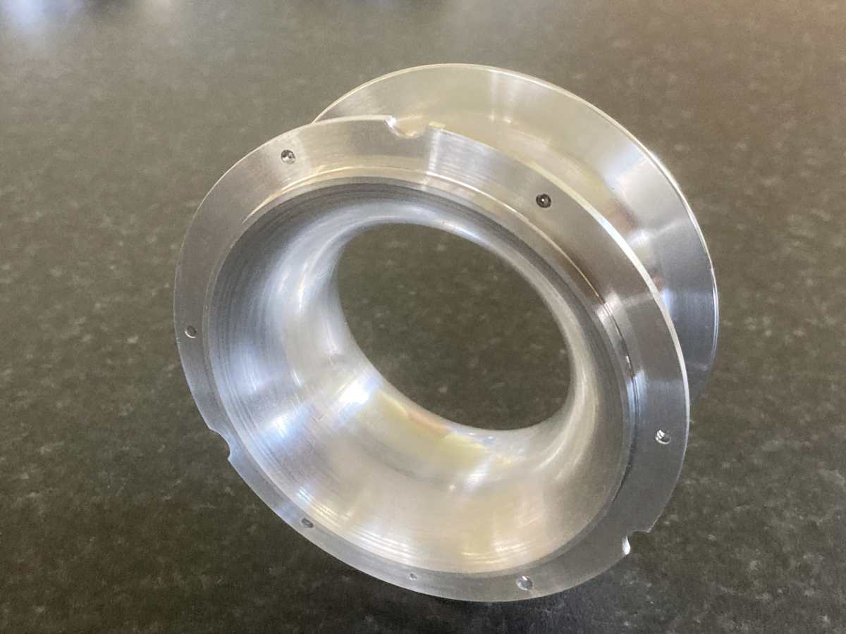
(Fascinating fact: the finished intake only weighs 15% of the blank that it started from!)
Here it is fitted to the diffuser cover:
The last job on the intake was drilling and tapping some holes at an odd angle for the securing screws for the fairing:
Done.
That’s all the major components machined!