
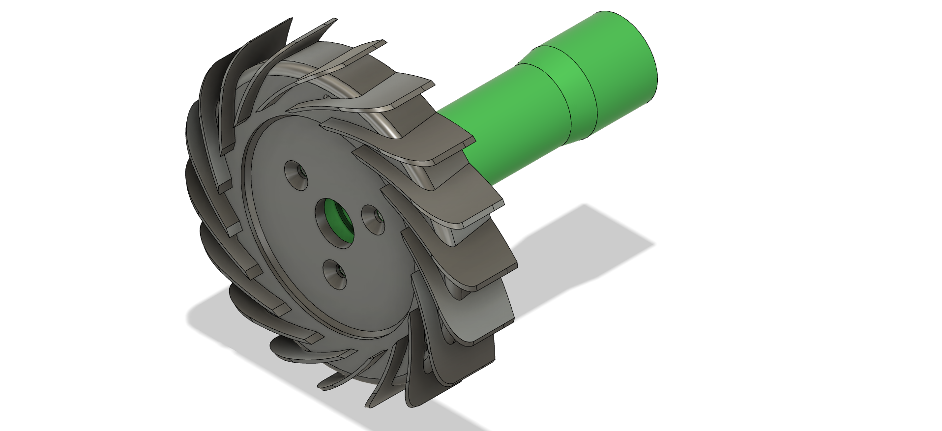
These static parts form the ‘backbone’ of the engine. The shaft tunnel (green in the image below) holds the shaft bearings, secures the shaft assembly to the diffuser at the front of the engine, and centralises the turbine inside the NGV assembly at the rear.
The diffuser (grey in the image below) surrounds the compressor wheel. It is a series of vanes that form air channels that gradually increase in area. They take the air that is spun off the edge of the compressor wheel at high speed and gradually slow it down, which increases its pressure. It also turns the airflow through 90 degrees towards the combustion chamber.
The shaft tunnel and diffuser hub are made from 6082 aluminium. In this design, the vanes are made separately and fitted into slots in the hub.
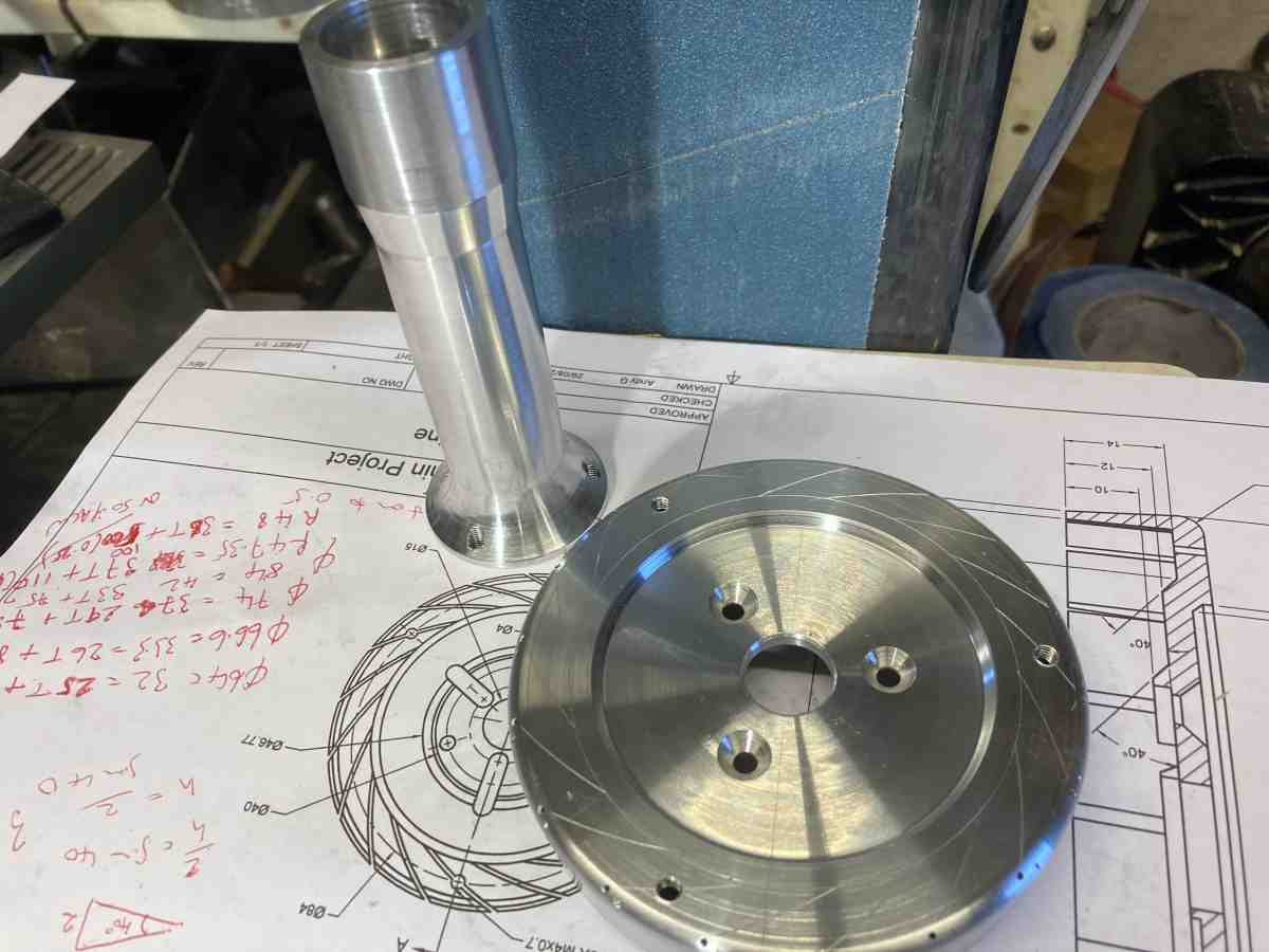
The shaft tunnel needs bearing seats at each end that are true to each other, and to the mounting flange.
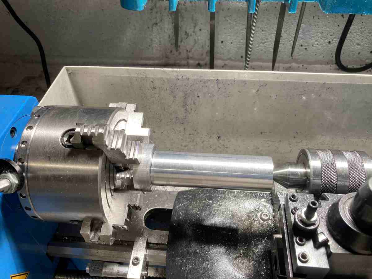
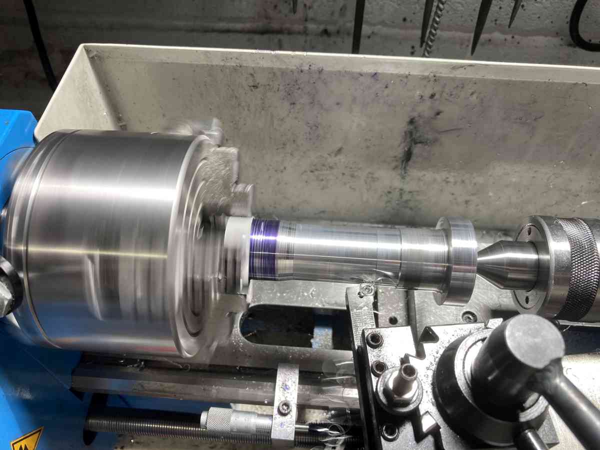
I set the stock up with tailstock support and machined the (parallel) rear section first, taking most of the stock down to the finished diameter of the parallel section:
I replaced the tailstock support with a fixed steady running on a part of the tunnel that would later be machined away and machined the rear bearing seat and drilled the central hole part way through.
This gives a part where the rear bearing seat is concentric and true to the OD and the rear face.
When it is flipped around in the chuck (gripping carefully on the finished rear section) and adjusted so that the OD is running concentrically and true it means that the rear bearing seat is automatically true.
I needed the steady again to machine the front face, front bearing seat, the locating diameter and to finish drilling / boring the through hole.
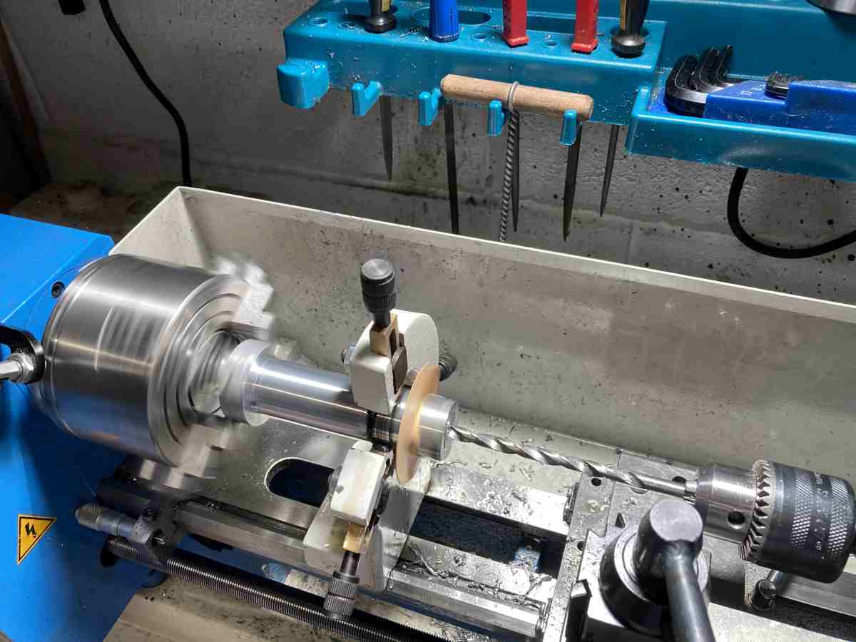
I could also drill the tapping size holes for the three mounting screws using my toolpost spindle without disturbing the setup.
I’d already made a plug to fit in the front bearing seat that would take the tailstock centre to hold the part while cleaning up the outside of the tunnel (it’s not essential that this section of the OD is absolutely true to anything).
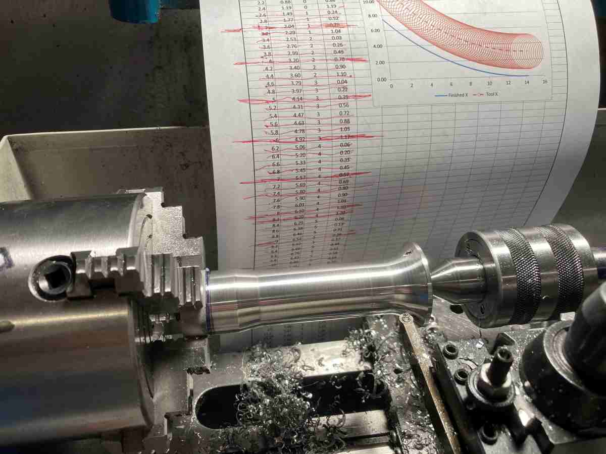
There’s a non-critical curve at the front of the section. I used this as a test piece for machining a curve to co-ordinates (‘machining by numbers’) as there are a few critical curves that will need machining later on. It proved my spreadsheet worked, and that I could use a 3mm radius tool without too much chatter.
Diffuser Hub
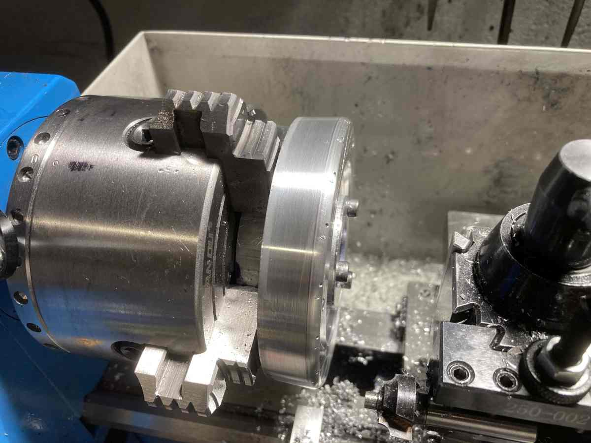
I machined the rear of the diffuser “hub” first. This was trickier than I though it should be due to the need to switch between tools to get into the various contours.
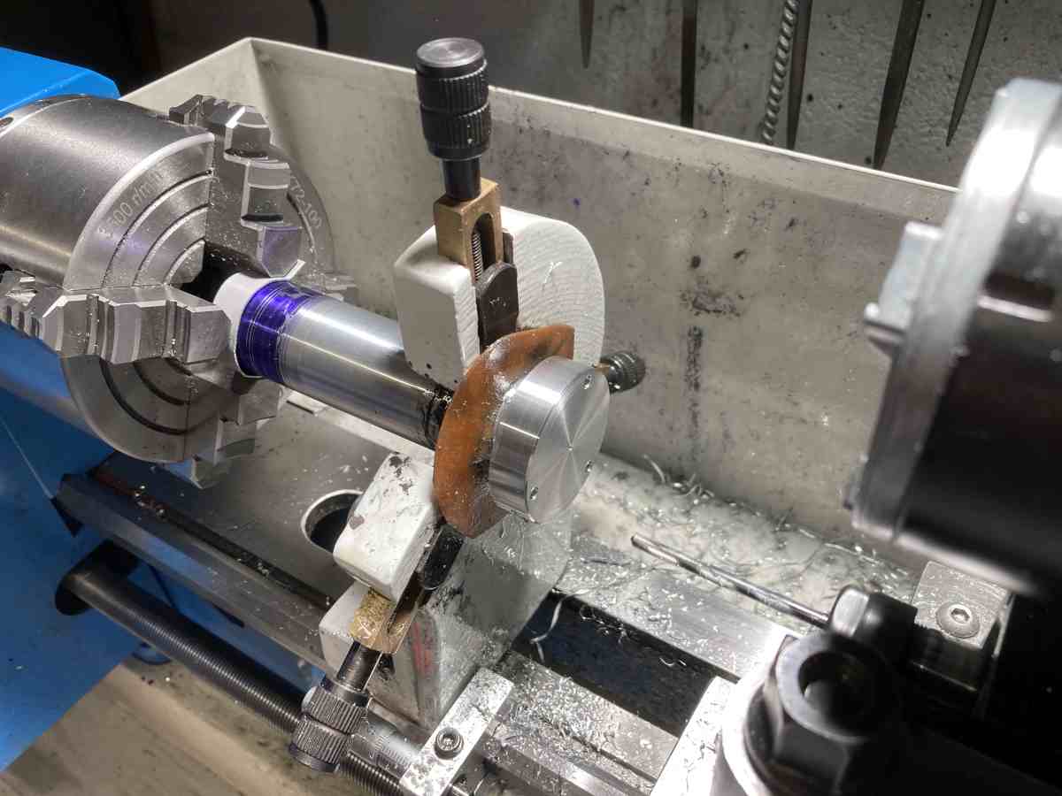
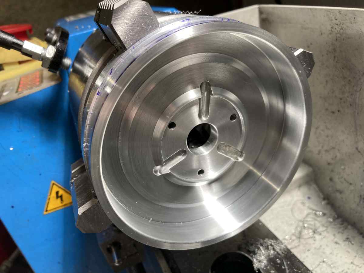
The three radial grooves allow air to bleed into the shaft tunnel to cool / lubricate the bearings. There will be a small pipe trapped in one of the grooves that dispenses an oil/kerosene mix into the airflow. The cooling air grooves were milled using my toolpost spindle while the part was still mounted in the lathe (along with drilling various holes – it really is handy!).
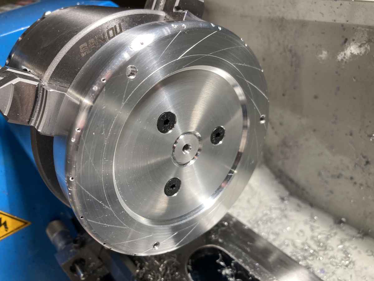
The part was mounted on a mandrel to machine the front face to try and keep the front and rear faces parallel. I used the 3 mounting holes initially, as I wanted to keep access to the centre point for marking out the diffuser vanes after the outer part had been machined. (I was pleased to see that there was almost zero axial runout after flipping it around.)
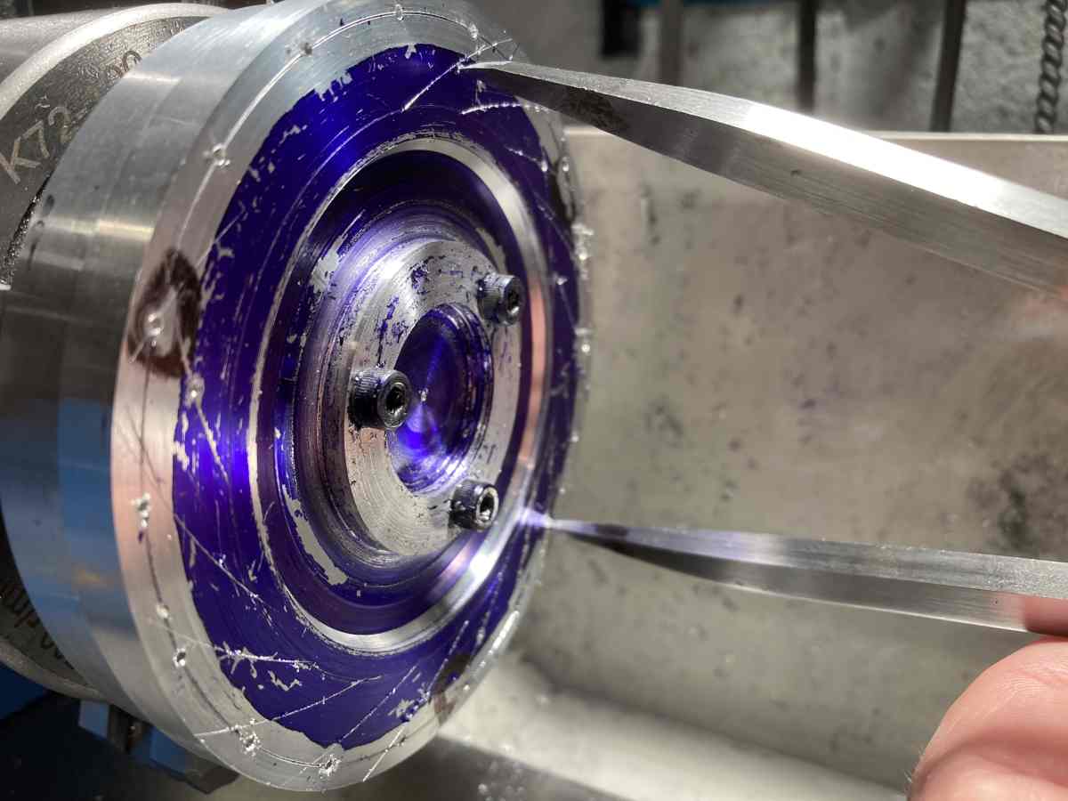
I thought I’d be clever and use a drill to gently mark the centre of each vane to help with marking them out – the centre of the radius falls just inside the edge of the diffuser disc. I though I would lose the marks when machining the radius on the outer edge of the diffuser. I would have done if I hadn’t drilled too deep though . I suspect the marks are annoying, rather than a problem, but I can fair them with epoxy later.
While I was at it, I tried to be really clever and drill a 1mm hole where each diffuser vane would met the edge of the ‘hub’ in the hope that this would give me ‘half a hole’ to give the saw somewhere to start when cutting the slots for the vanes. In another brain fart, I machined these *inside* rather than *outside* my reference diameter. (Luckily they are still on the line of the vanes.)
To add insult to injury, I managed to break a 1mm drill deep in one of the holes… 🙁 Hey ho…
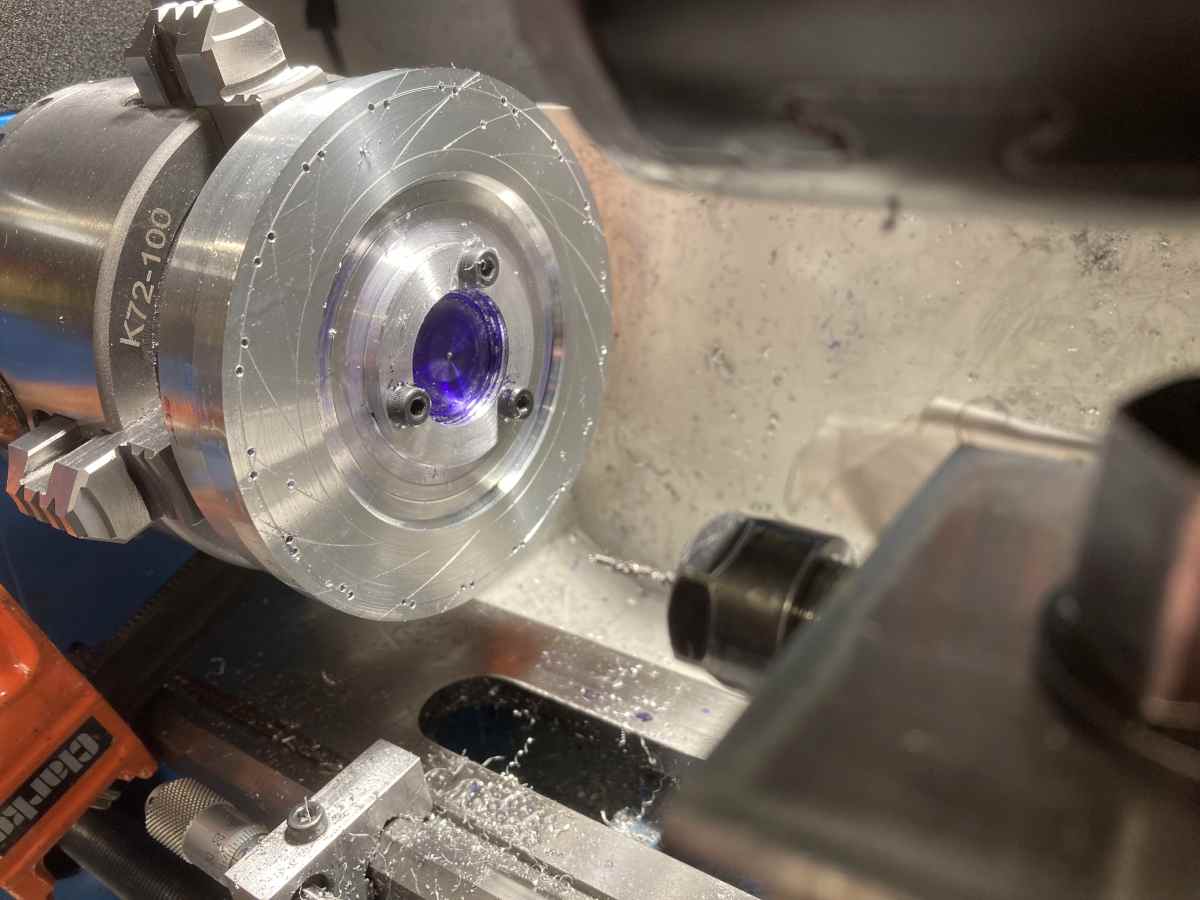
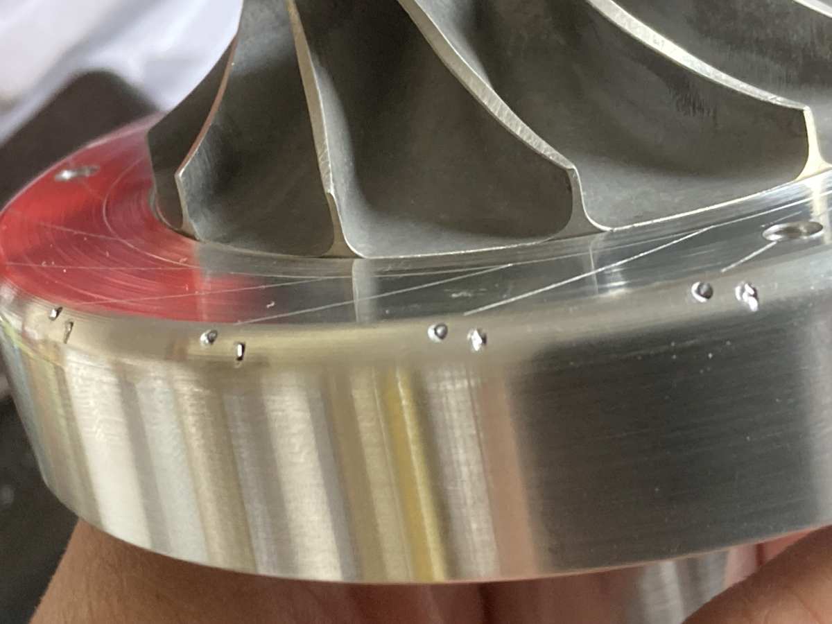
The outer edge of the diffuser is tapered with a 3mm radius on the front edge. I cut the radius using a router cutter as a form tool which worked surprisingly well.
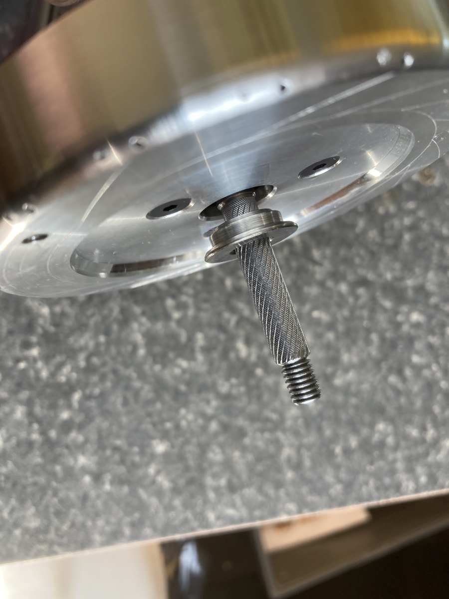
I then drilled and tapped the centre of the mandrel so I could clamp the centre of the hub to machine where the three mounting screws were and countersink their holes. It was then re-mounted it using countersunk screws to take a light skim off the area behind the compressor.
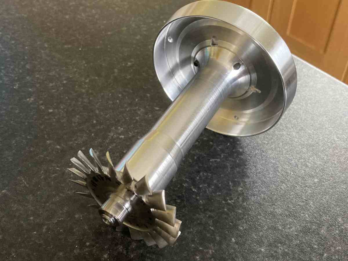
I could then have a trial assembly
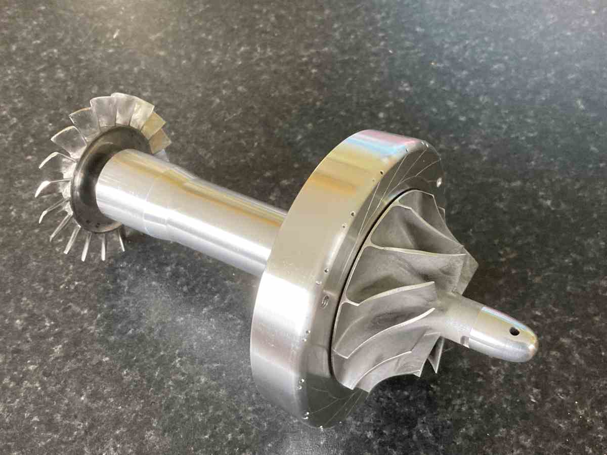
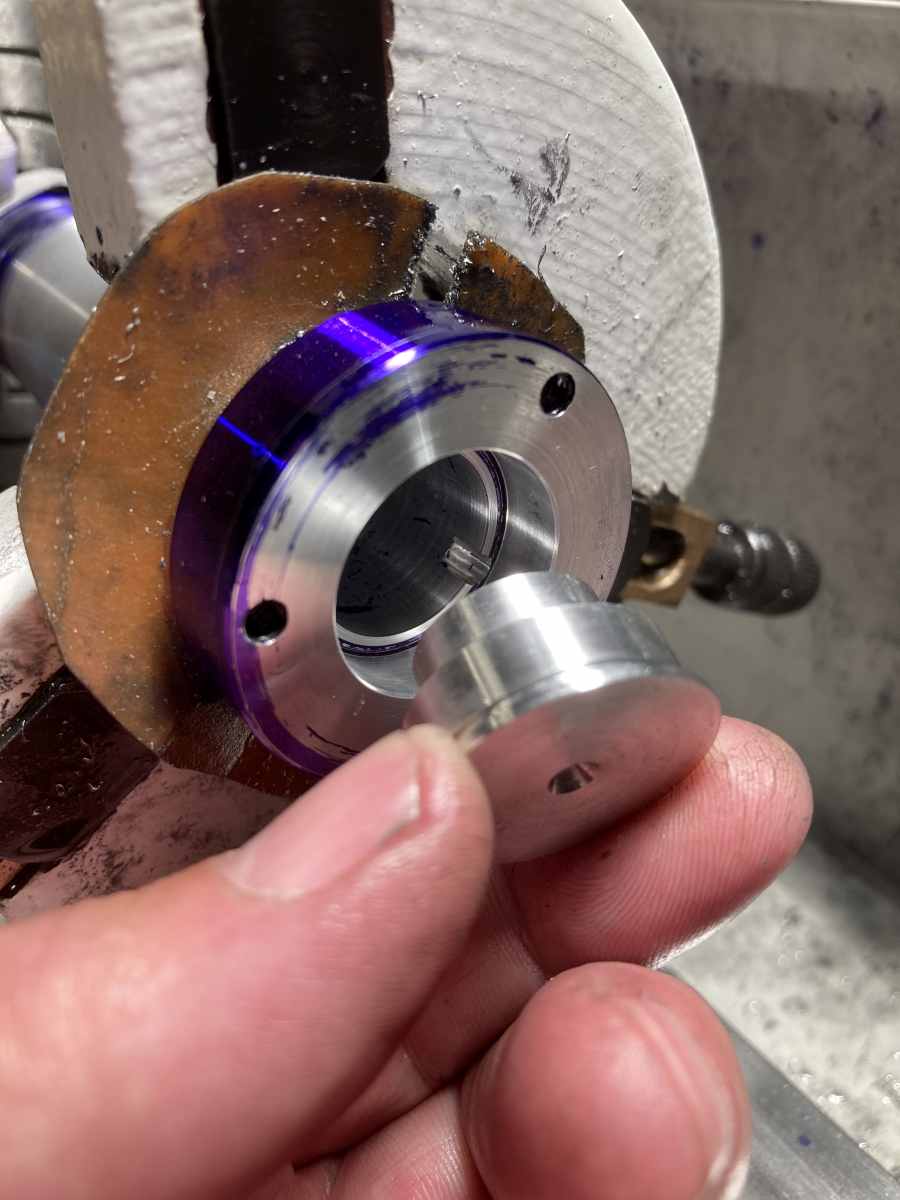
The front spacer needs adjusting to bring the edge of the compressor wheel level with the face of the diffuser. Feeler gauges and a fingertip seemed to be the best way of measuring the height of the compressor to see how much needed to be machined off the front spacer:
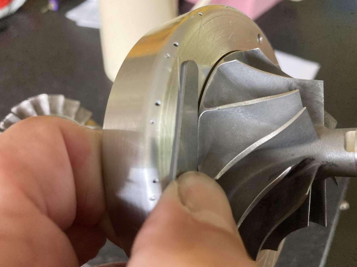
With a new front spacer…
…the edge of the compressor disc is, as near as I can tell, level with the surface of the diffuser.
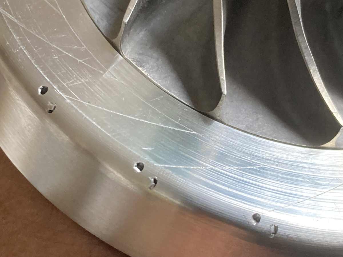
(The shallow holes in the edge are where I drilled too deep when marking the centre of curvature of the vanes; If the other holes had been drilled in the right place, they should have been split by the edge of the hub, but they’ll be cut through anyway when I make the slots for the vanes.)