
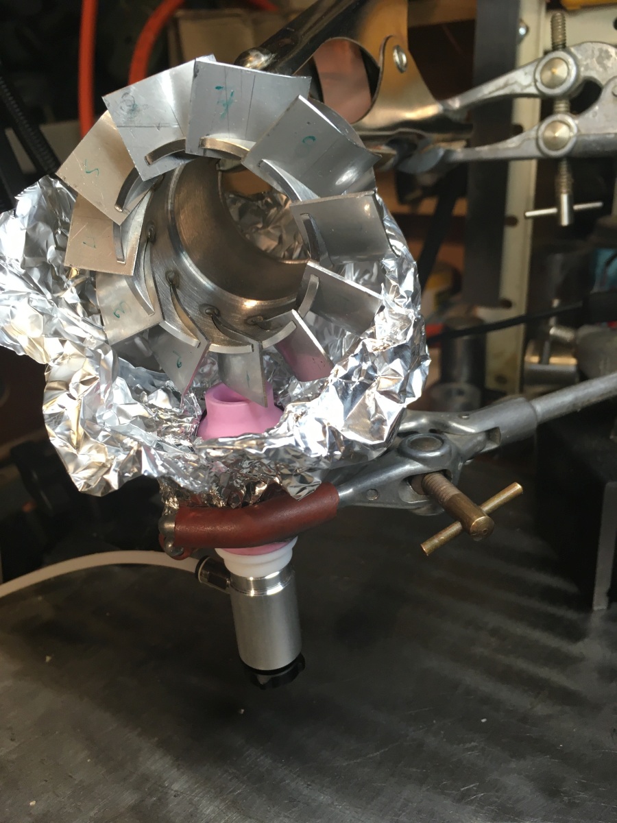
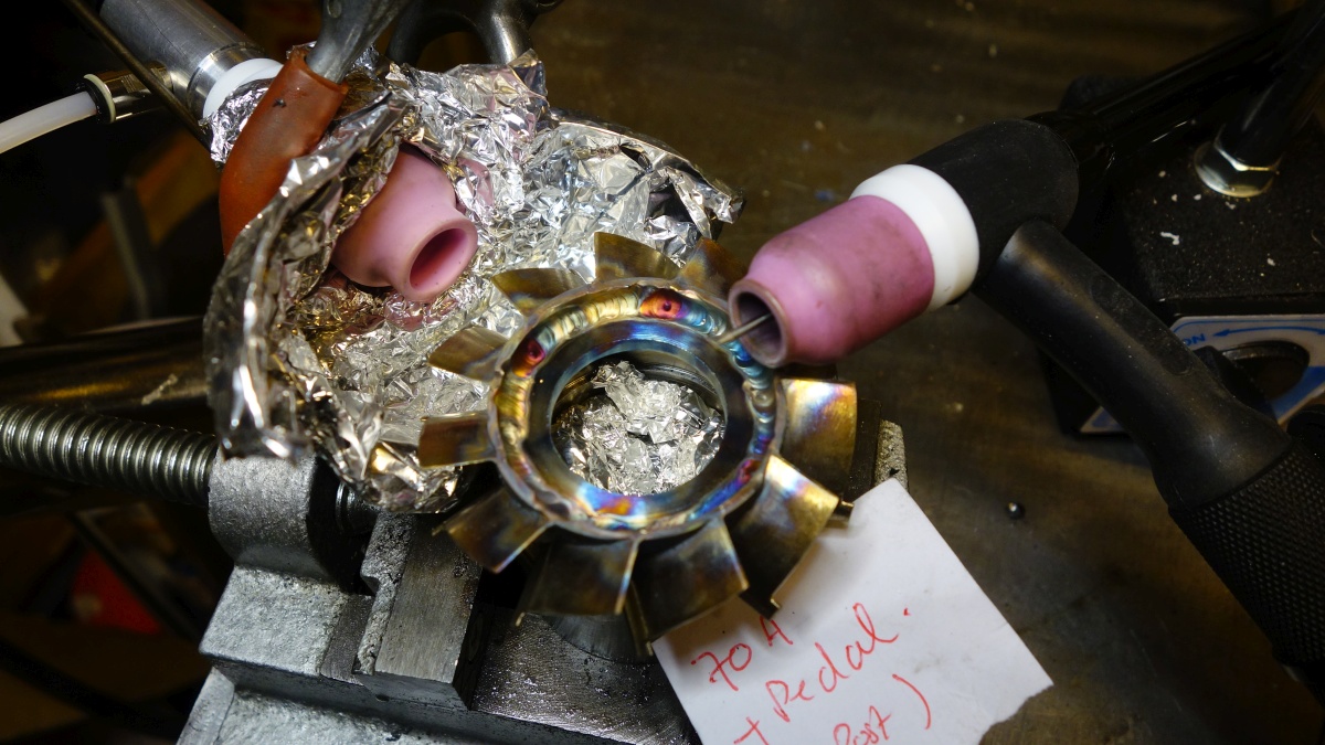
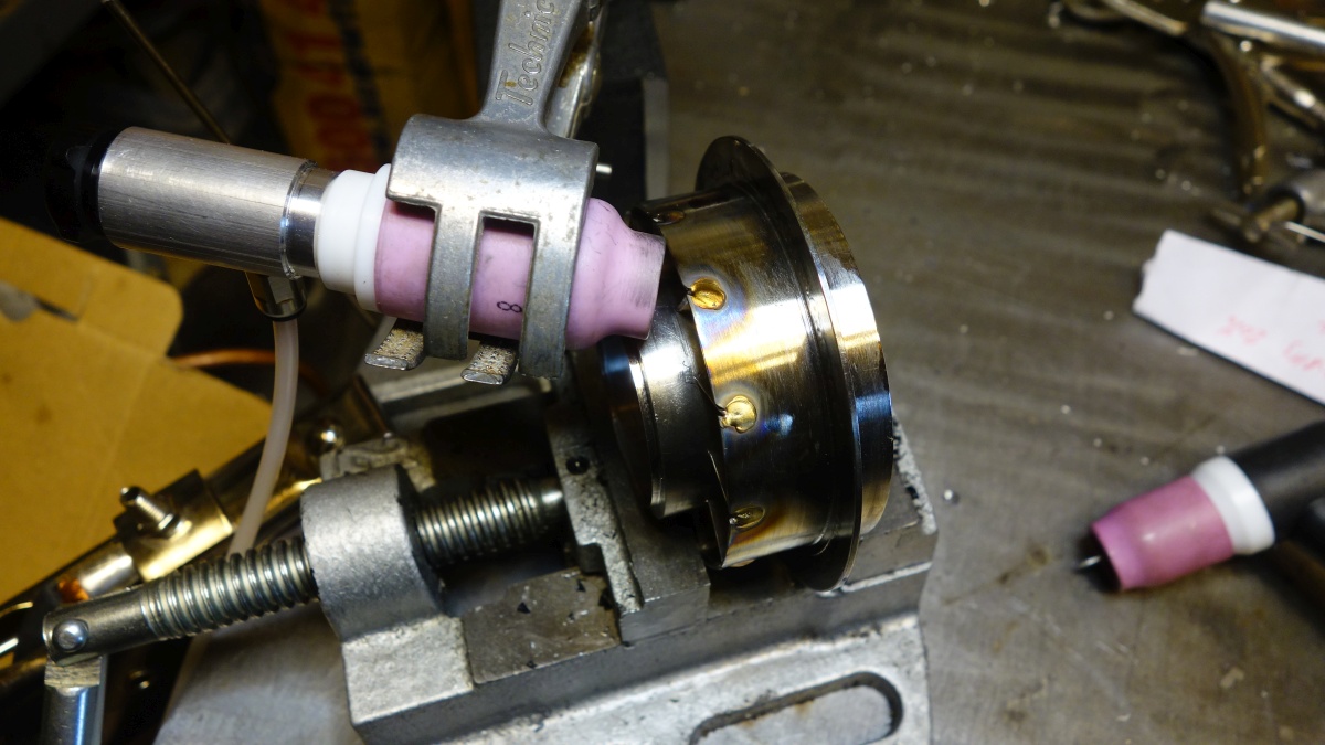
I was now ready to weld the NGV together. After asking for advice on how to purge this part on the MIG Welding Forum, the advice I got was to use a second TIG welding ‘gas lens’ to stream argon onto the outside of the part while the blades were welded on the inside of the inner ring.
This is the arrangement I used, and it worked very well (the gas lens for purging is at the bottom, with the aluminium foil to hold the shielding gas around the hot area):
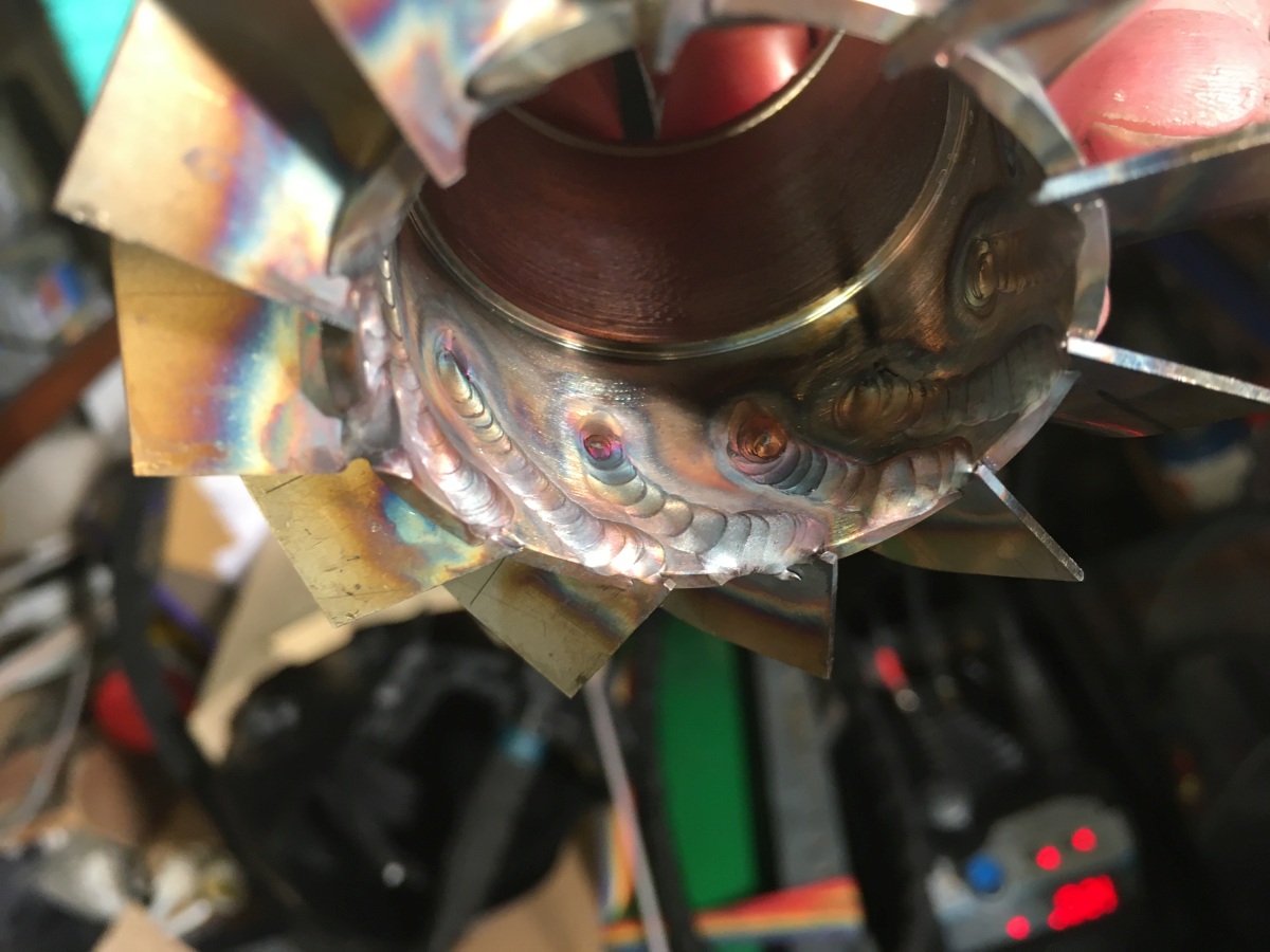
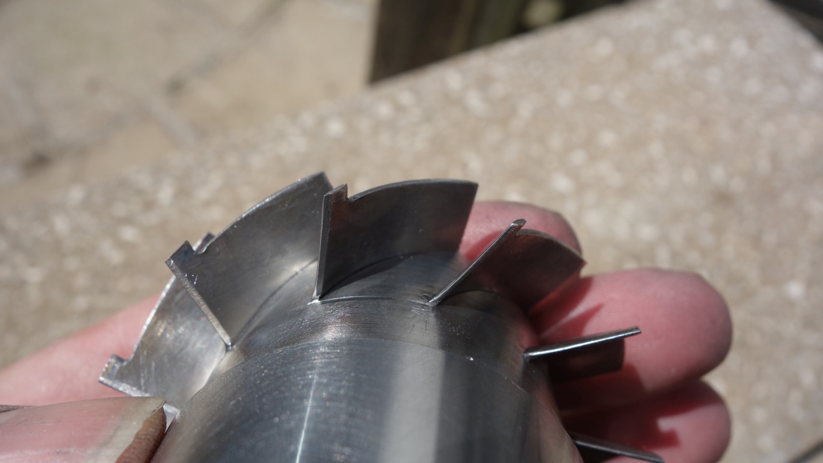
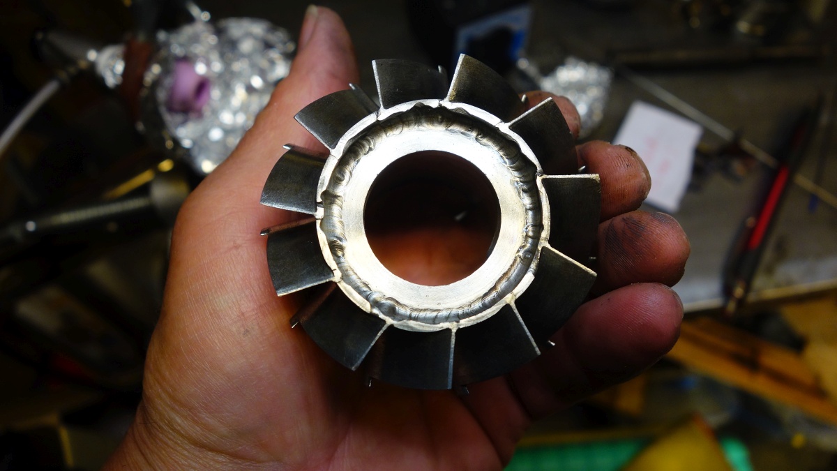
After welding all the vanes to the NGV inner:
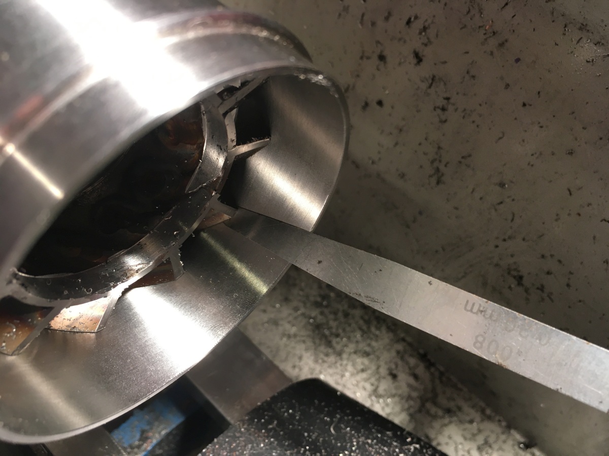
I then put the welded assembly back in the lathe trued up the front and rear edges of the vanes and skimmed the down to fit in the NGV outer, leaving ‘tabs’ to weld at the leading edges.
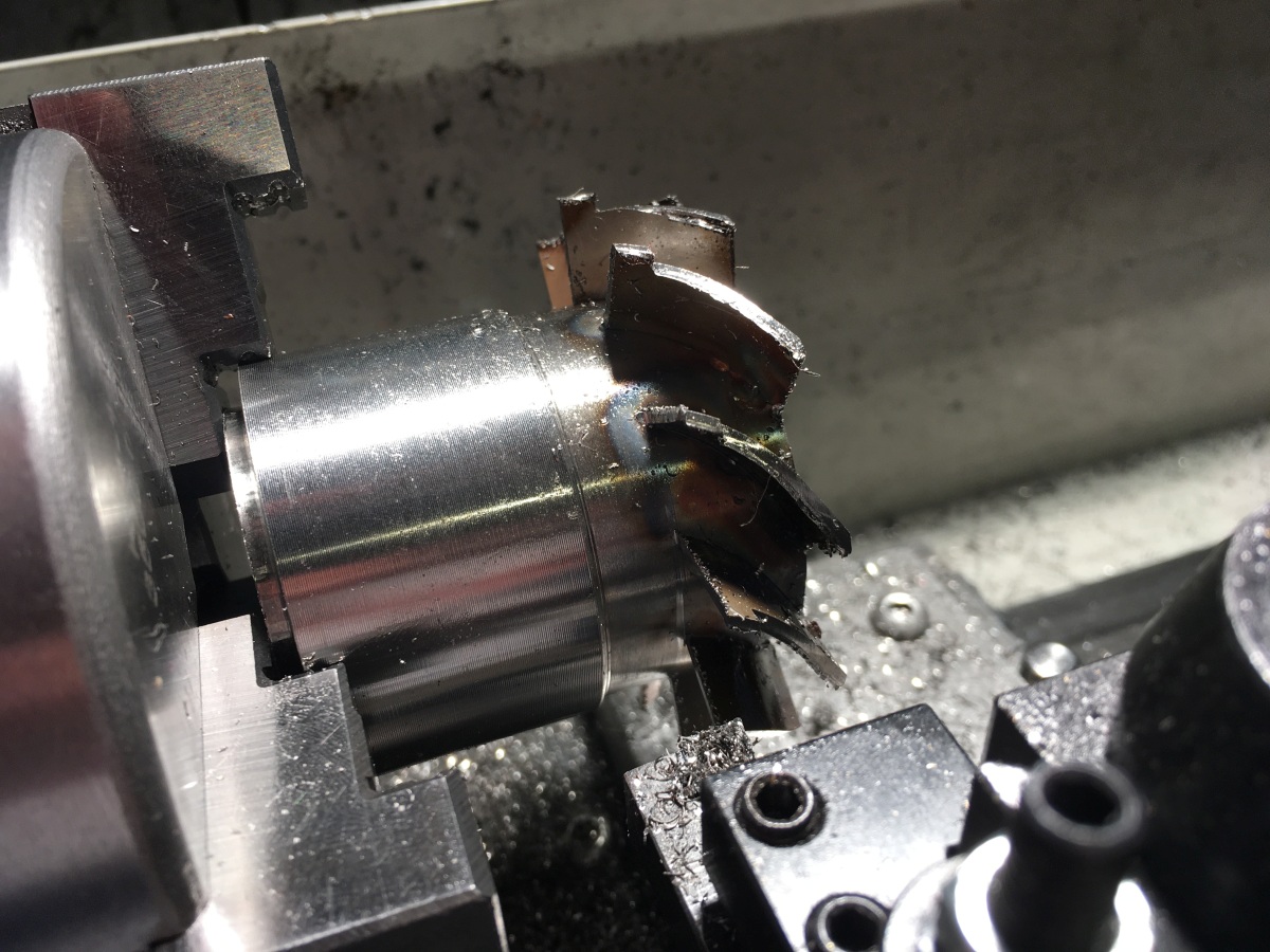
The vanes are only welded to the outer ring at their front edge, and there’s supposed to be a bit of clearance between the outside of the vanes and the outer ring to help avoid the thing distorting in use (the vanes get *very* hot)
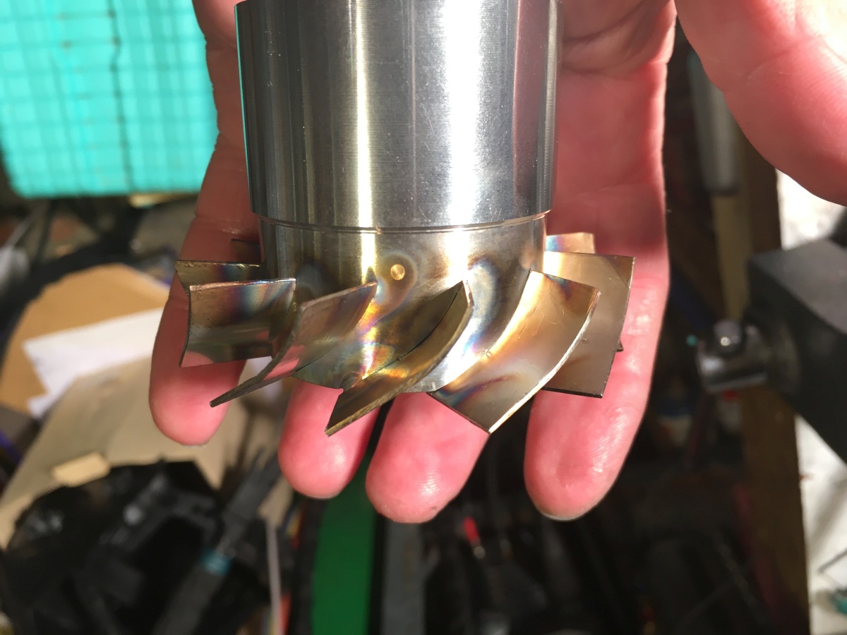
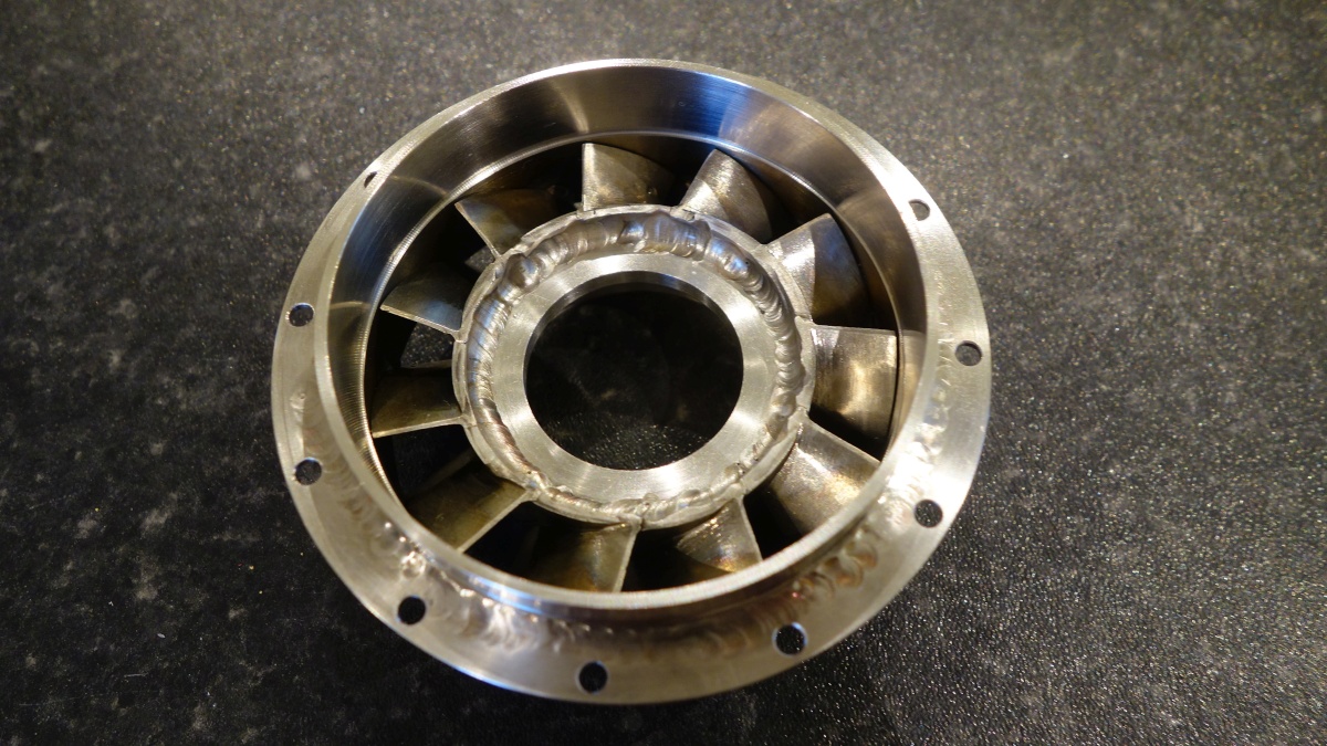
After a bit of cleaning up:
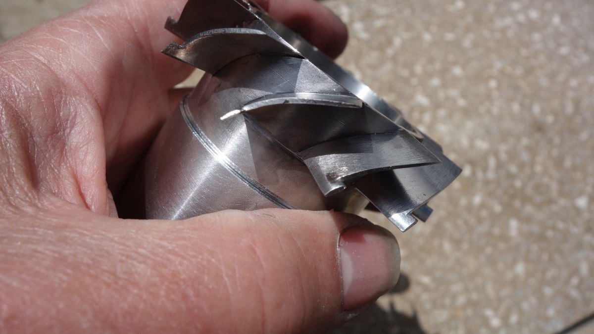
I also cleaned up the bore so that the ring that supports the turbine shaft tunnel can be fitted.
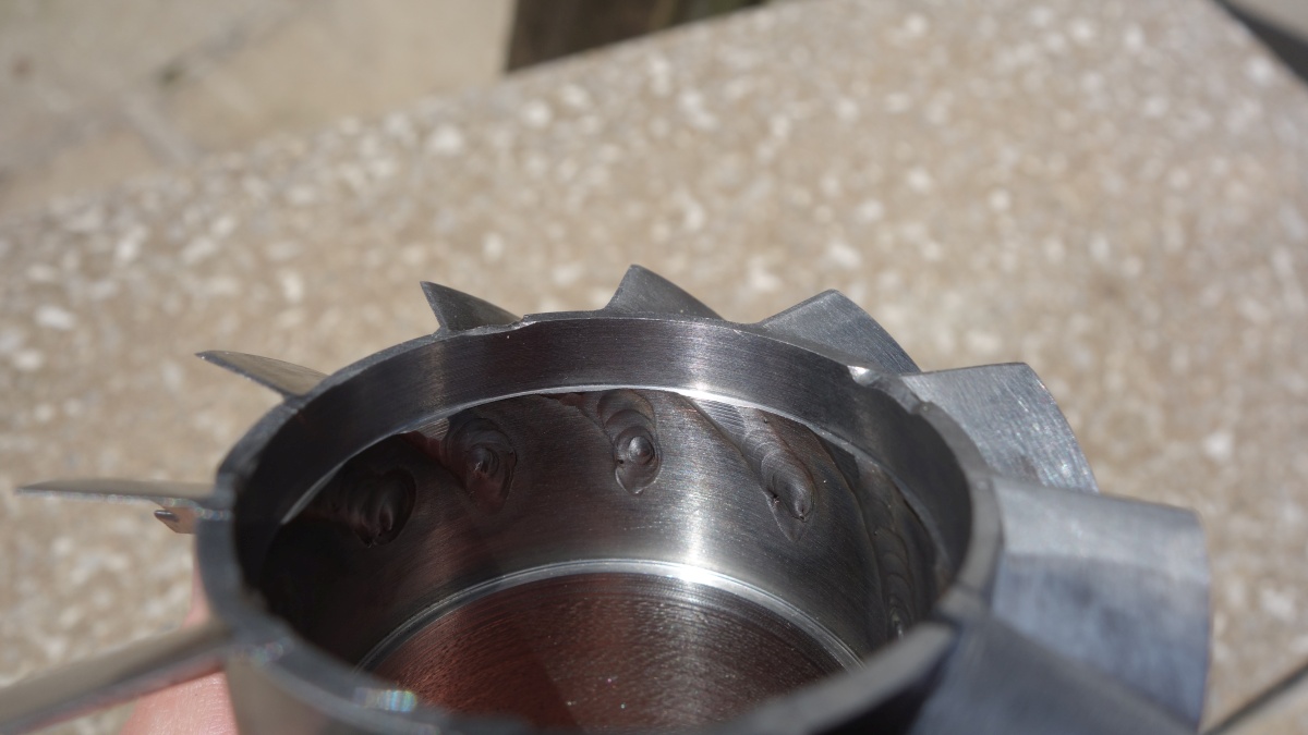
I machined up the support ring and used a similar setup as before to weld it into the inner ring.
(Not the best looking welds in the world…)
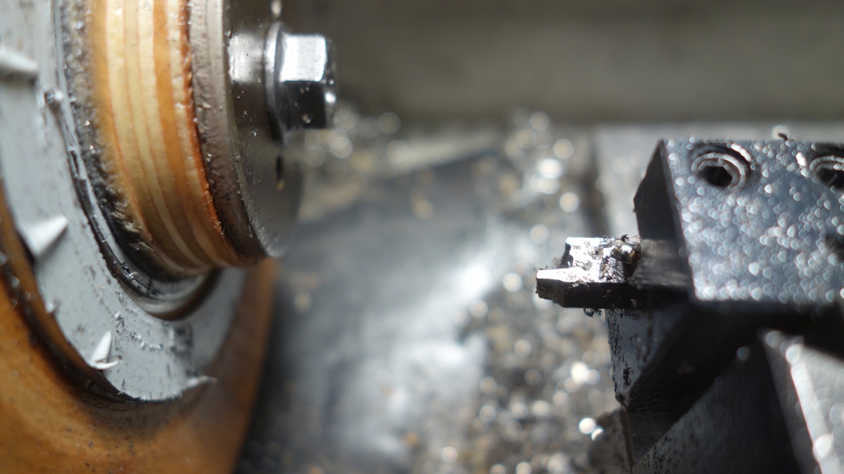
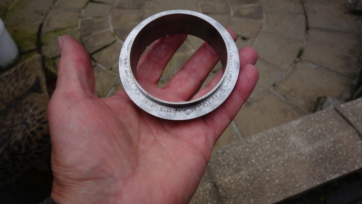
The outer part of the NGV is mounted to the engine casing with a welded flange. I trepanned a ring out of 1.5mm stainless for this (not an entirely happy experience!):
I thought I was being clever, as I machined the flange to be a very close fit on the NGV outer so that it could weld cleanly without any filler.
Lesson learned here was to let it cool down completely between welds! I was very careful to alternate the welding from side to side, and had hoped that by having a tight fit-up and an autogenous weld that I might be able to avoid too much distortion, however I don’t think I let it cool it enough between welds and ended up squeezing the bore down by 0.3mm under the flange! It did stay circular though.
Back on the lathe and centralised as best I could
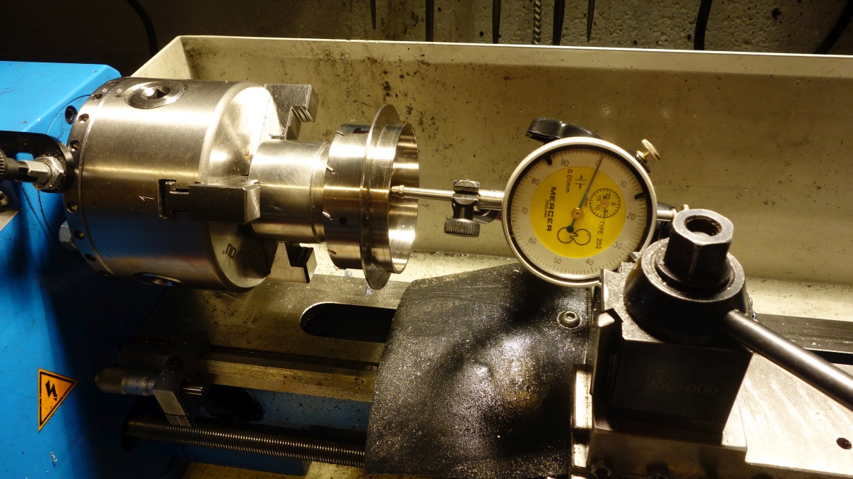
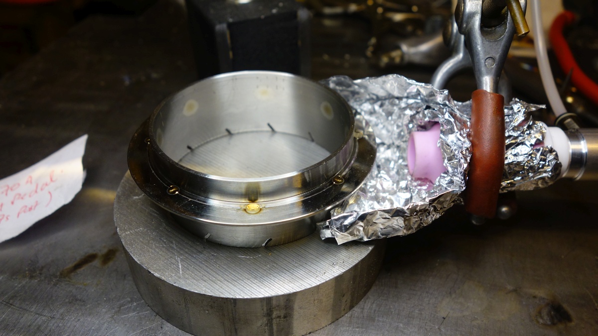
The leading edges just need to be tack welded to the outer. (I used an extra gas lens for shielding again, but I’m not sure it was necessary):
I then skimmed the bore true and parallel again.
The vane clearance isn’t terribly uniform around the NGV, so I would guess the inner will go slightly off centre when it heats up – I would have done better to shim between the vanes and the outer ring to maintain the clearance while welding, but hey-ho.
So this is where we were up to – the combustion chamber and NGV fully fabricated:
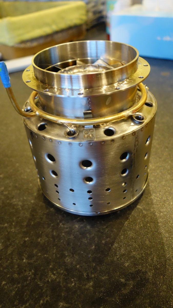
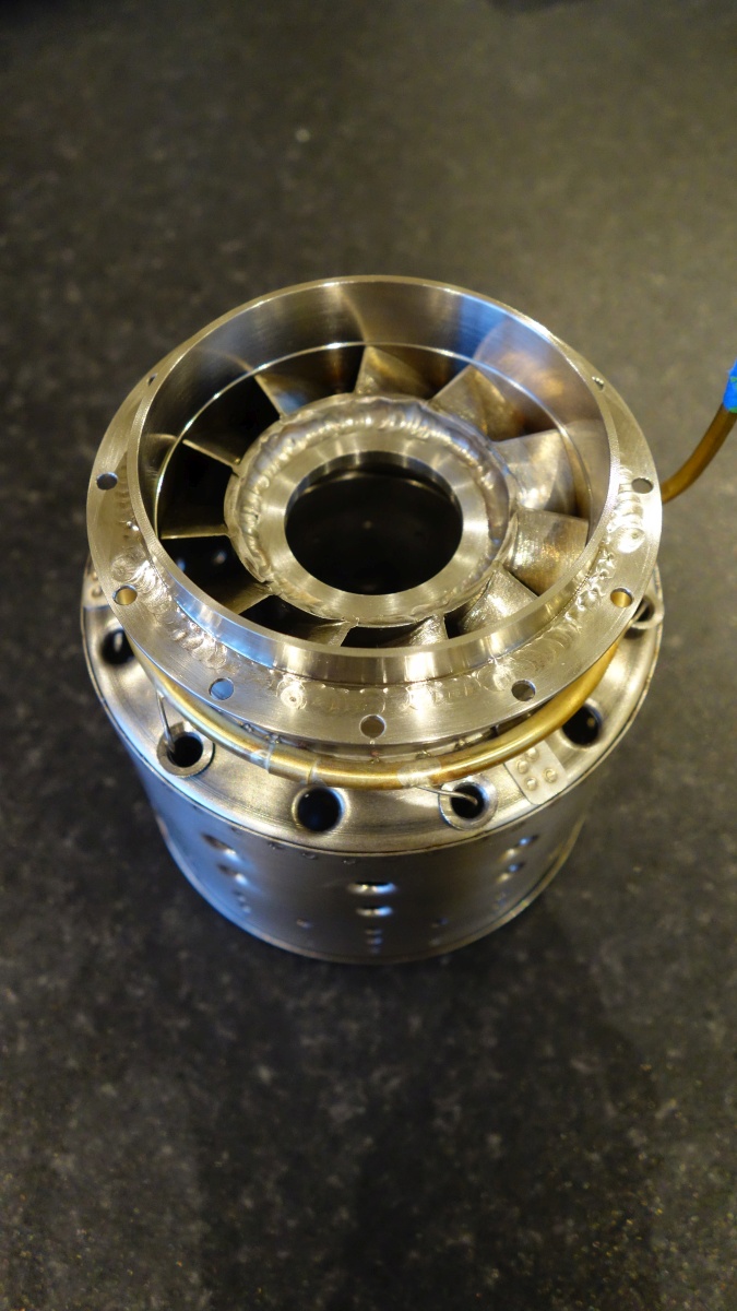
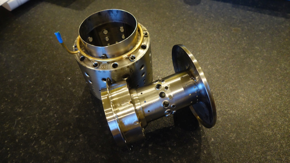
(The vaporiser tubes haven’t been fixed in yet and the fuel ring is just roughly positioned)