Now to the difficult bit…
The turbine wheel at the back of the engine sees ~600°C while under very high stress – engines this size typically idle at 30,000 RPM, and can run to over 100,000 RPM (I remind you that mine hasn’t even done 1 RPM yet!)
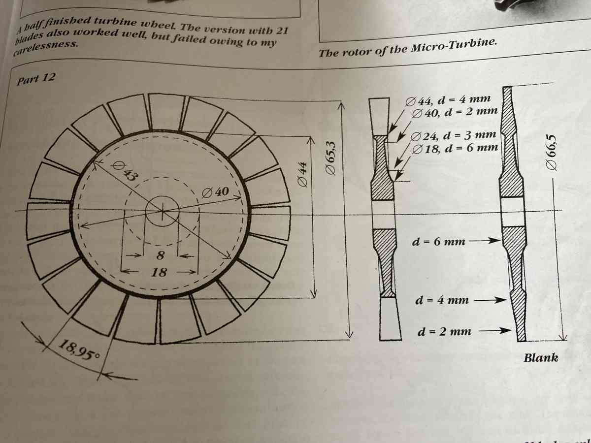
The best materials to use for the turbine disc (from a performance point of view) are nickel alloys – Inconel 718 especially. I think that all commercial model jet engines use vacuum cast Inconel turbines, but DIY ones are made by machining a disc to a tapered profile, cutting slits in the edge of the disc to form blades and then twisting and grinding these to the required shape.
I had been unsuccessful in trying to get hold of any suitable Inconel, and was doubtful whether I could machine it anyway (although people in the GTBA report that they have managed to machine it OK) so had resigned myself to using 316 stainless (347 or 310 may have been marginally better, but I couldn’t find any of that at reasonable price, either). A stainless turbine would be limited to 80,000 RPM and would have a limited life due to creep.
I’d bought a couple of 10mm thick 316 stainless blanks, then I found two Hastelloy X discs on ebay – not as good as Inconel 718, but better than stainless!
These were 5mm thick rather than the required 6mm which (on crude calculations between Inconel at 105,000 RPM and 316 stainless at 80,000 RPM) will mean the red line will be ~95,000 RPM.
I bought one piece initially, cocked up one of the diameters when machining it, but luckily the other one was still there so I bought that too. Every cloud has a silver lining, however, and this has given me a dummy disc to practice on.
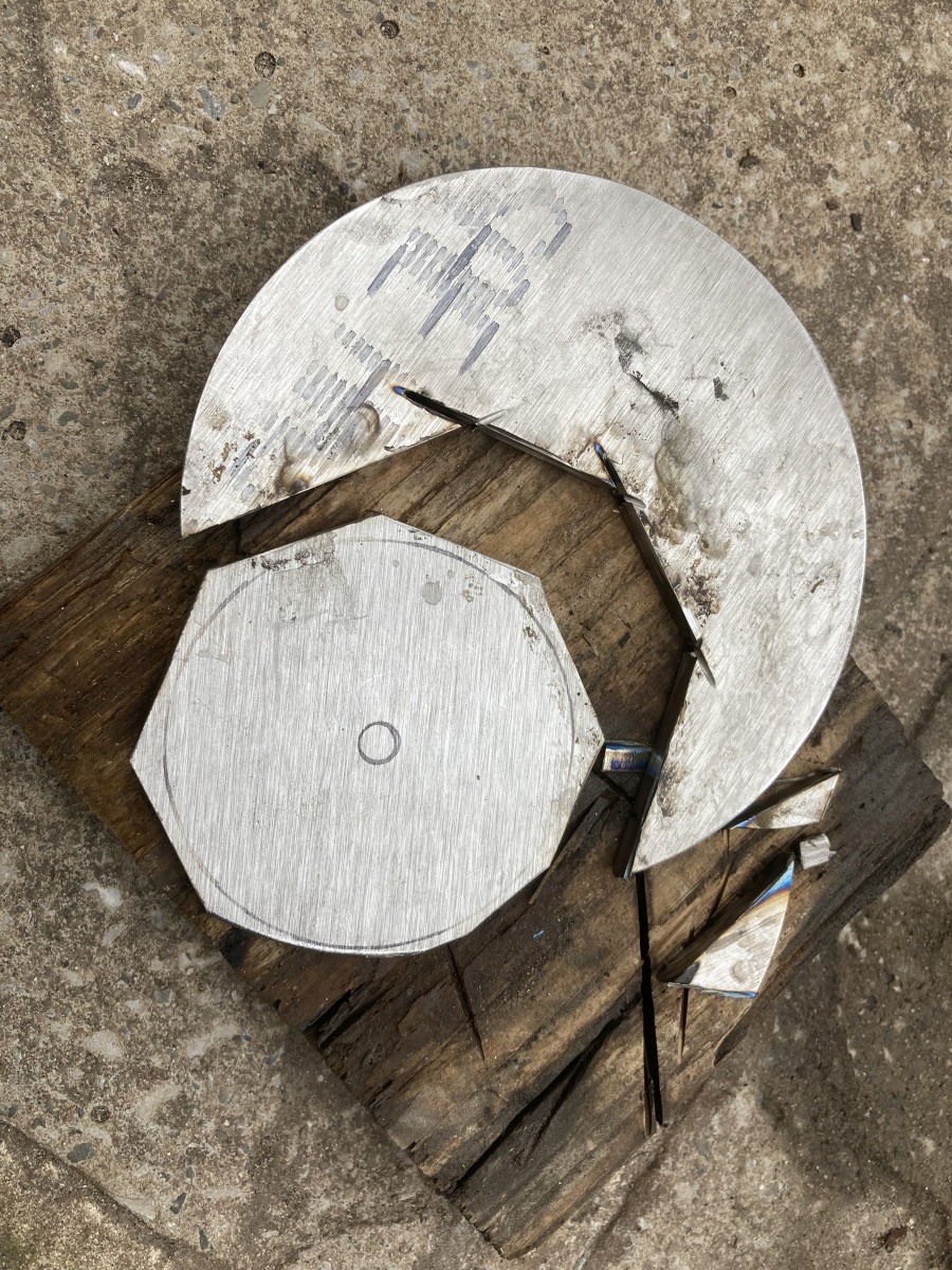
I cut a rough blank out of the disc with the angle grinder, trying to make something that I could chuck in the lathe fairly securely:
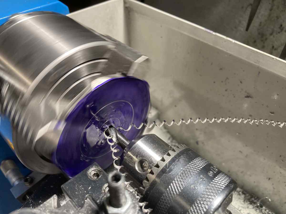
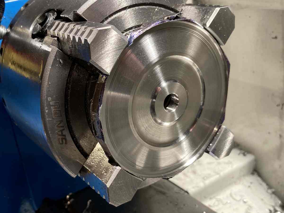
Drilling, boring & reaming the centre hole (HSS drill bits worked OK if really sharp and short to stop them winding up).
One face was turned roughly to profile while the blank was in the lathe, hopefully creating a face that is true to the bore. It actually machined OK – dead slow with positive rake carbide inserts and plenty of cutting oil – and keep it cutting!.
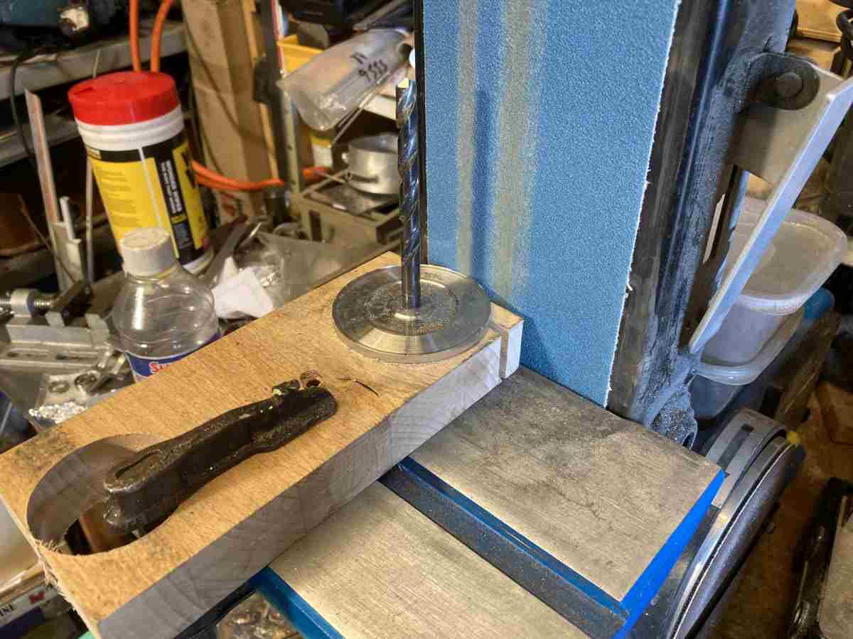
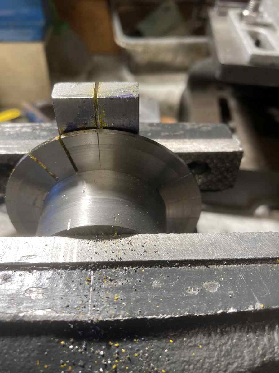
Then I removed it from the lathe and knocked the corners off the disc on the belt sander so it was kinder to the lathe tool when turning the OD.
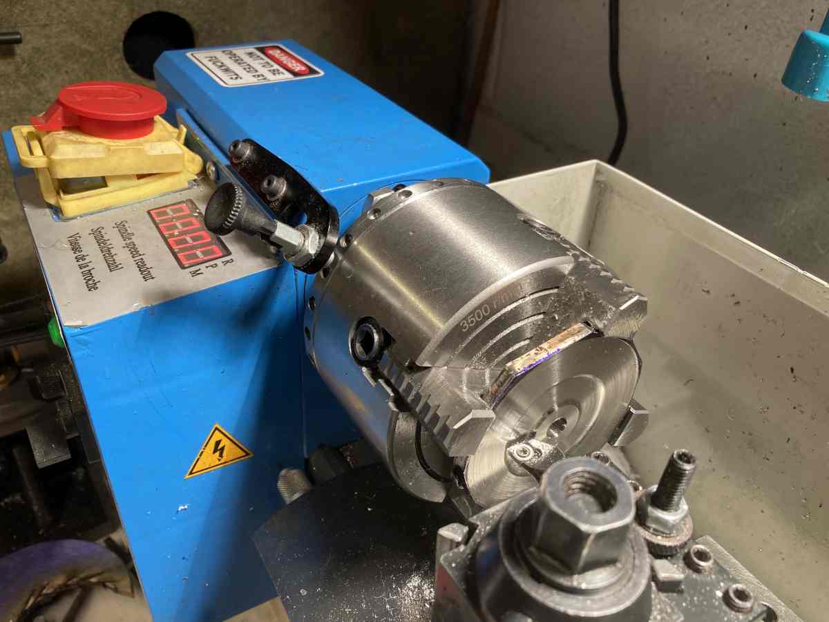
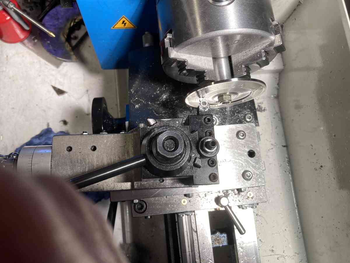
The disc was then re-mounted on an arbour in the central bore so the OD could be brought to finished size
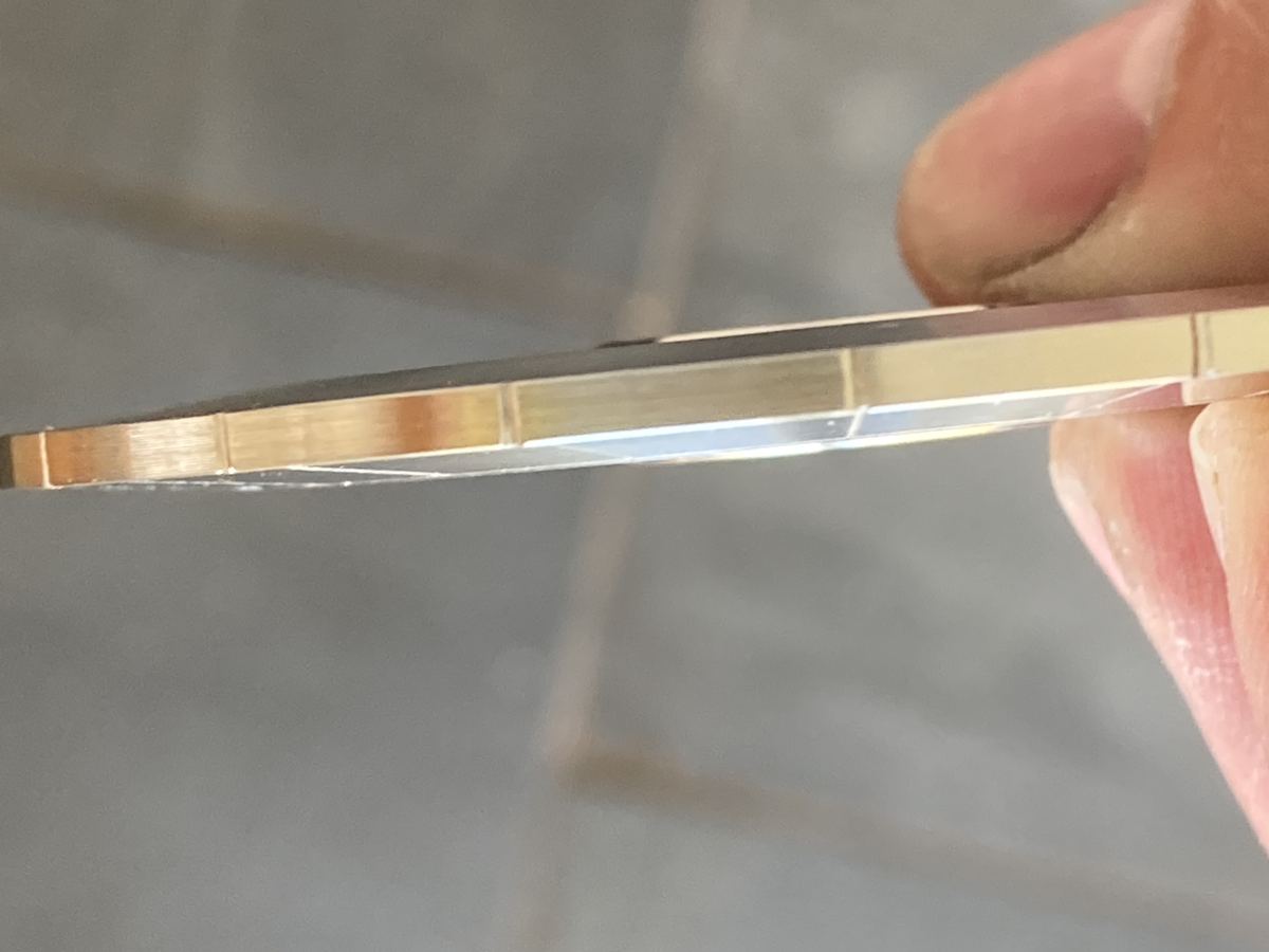
The second face was then turned to the profile shown in the book.
It was then reversed again and the first side brought to finished size. On the first disc I made, I tried to finish the first side on the first pass, but found that the plate bowed by ~0.01mm when the second face was machined.
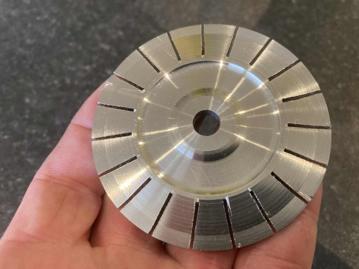
I marked out the cutting lines while it was still in the lathe:
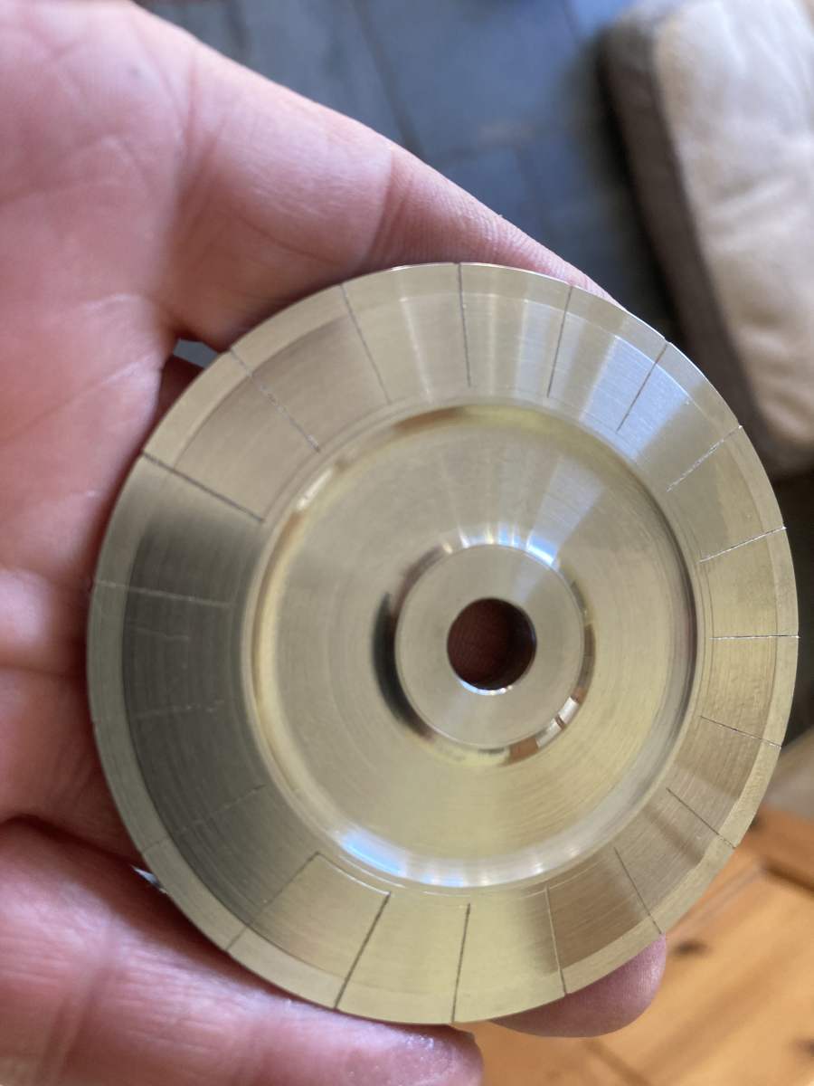
Slitting the disc into vanes was just done with a hacksaw. This stuff is fairly brutal on blades and they lose their edge very quickly (immediately if you try and saw quickly!). I found on the first few cuts of the practice disc that it was difficult to stop the hacksaw blade wandering once it had started to lose its edge (it would cut sideways better than it would cut down), so I made a little guide block to help keep the blade on line.
It took three [Starrett Red Stripe] hacksaw blades to cut the 19 slots in the disc (and I had made two discs, so that was 6 blades in all). It does say in the book that if you can cut 50mm per blade you were doing well!
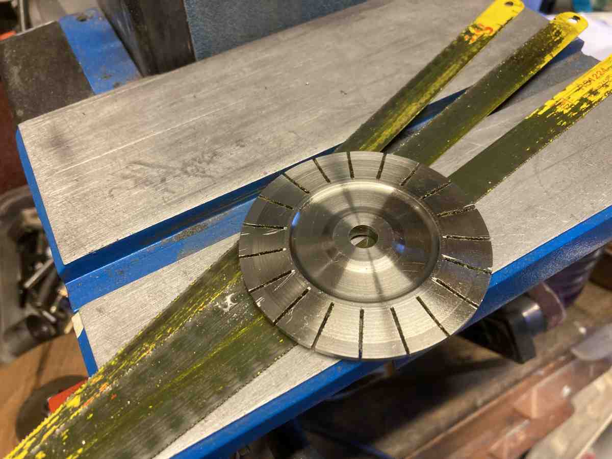
The next job will be to twist the blades…