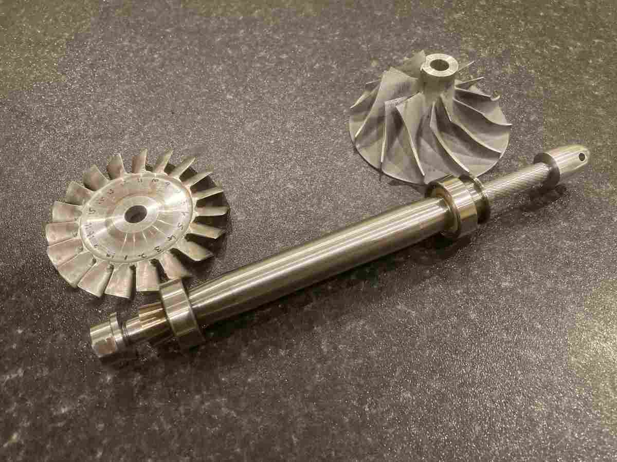
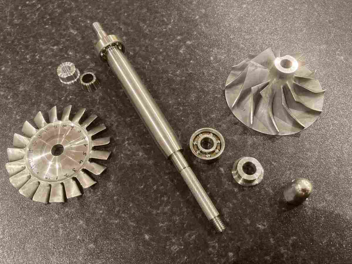
The turbine wheel fits on a shaft that passes through the middle of the engine to drive the compressor wheel at the front. It’s supported on a couple of ball races and both wheels are clamped onto the shaft with left hand threaded nuts. The whole thing needs to be as true as possible.
The shaft is chunkier than I was expecting and made of heat treated steel: 817M40T (EN24T). It needs to be stiff enough for its resonant frequency to be higher than the running speed of the assembly (to avoid the shaft ‘whipping’) and strong enough not to take a permanent set if it doesn’t run perfectly true (I learned from the book…)
It also has to transmit ~20 horsepower to the compressor wheel at full chat!
I made the clamping nuts first, trying to keep the tapped bore true to the clamping face.
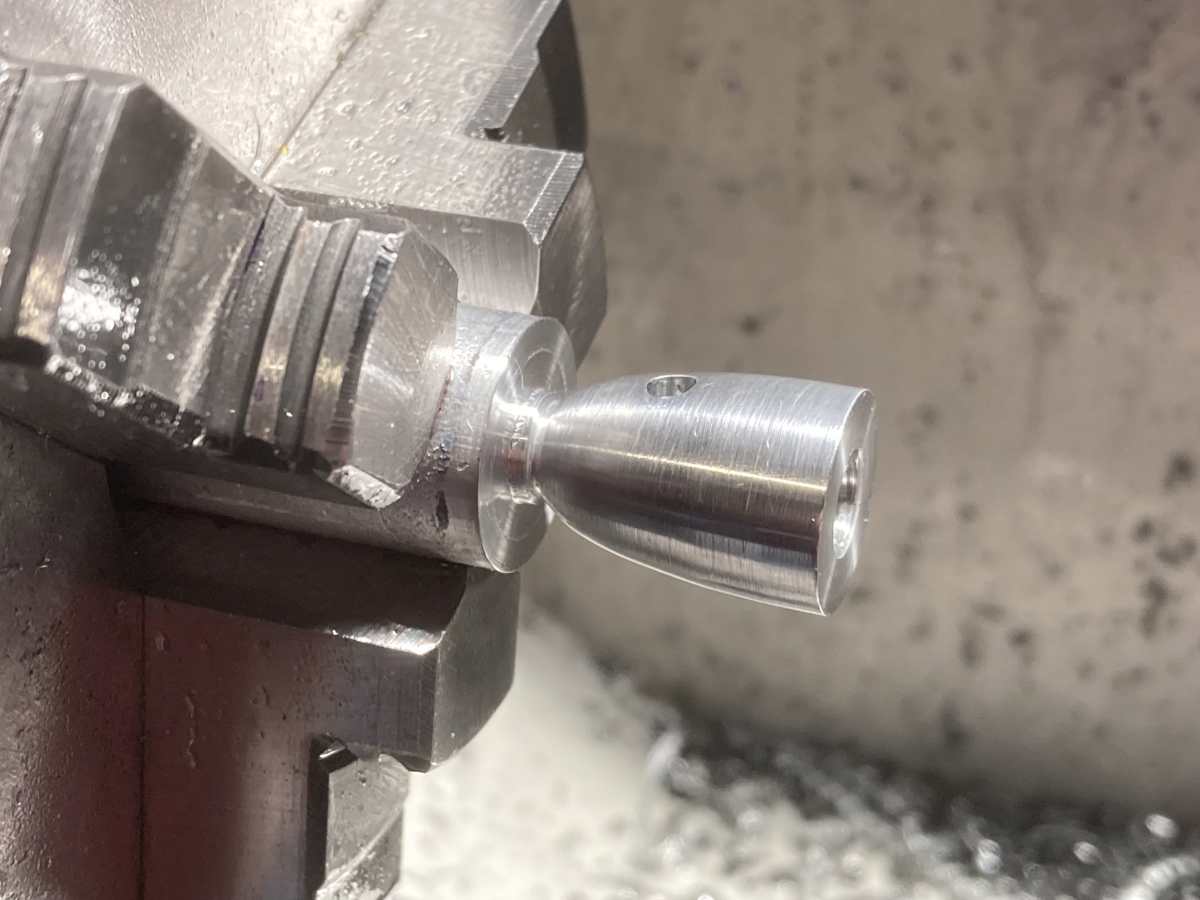
An aluminium spinner nut to secure the compressor wheel:
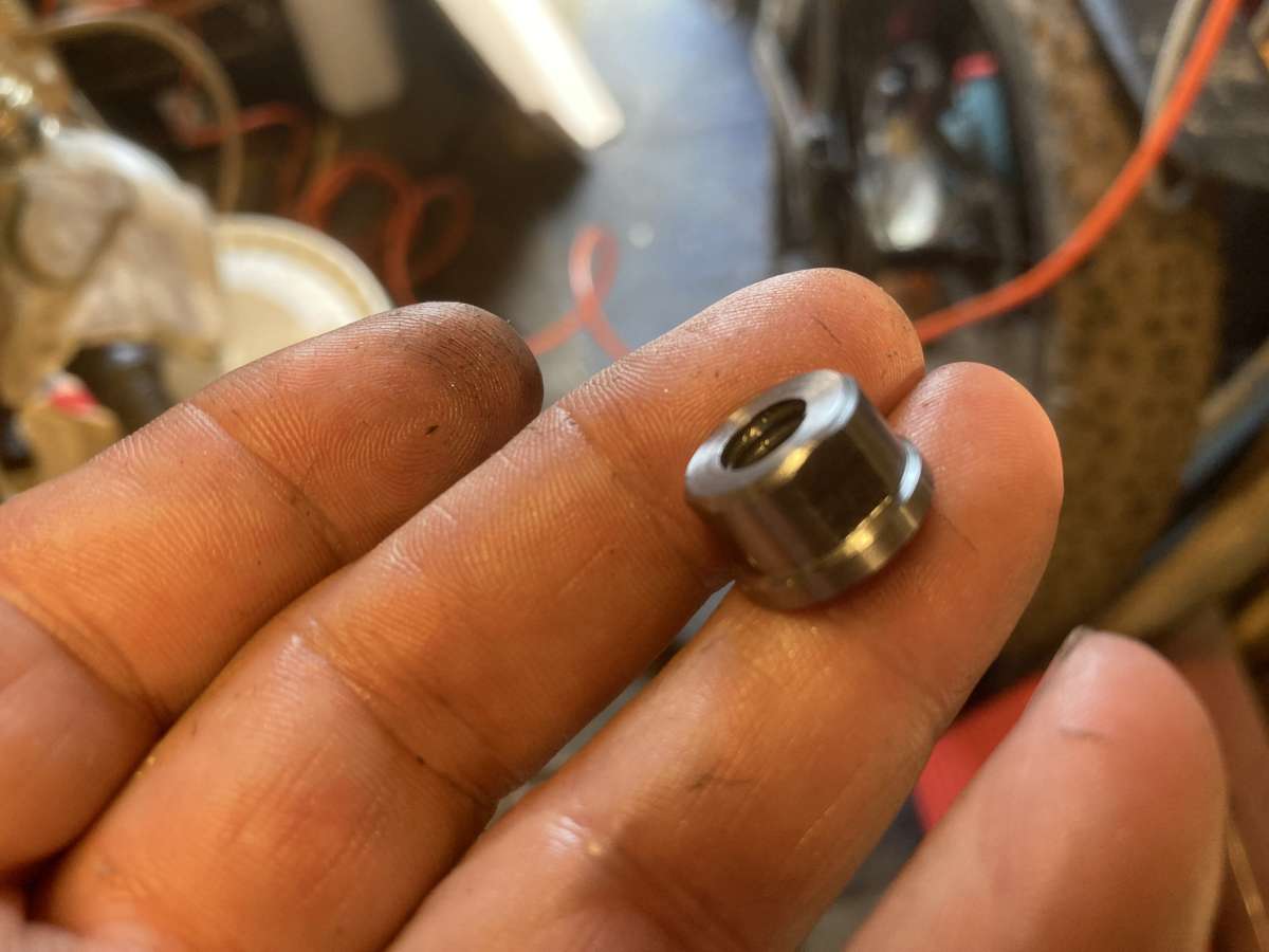
And a steel nut to secure the turbine wheel:
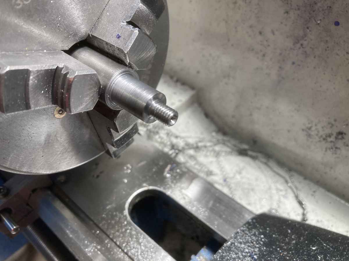
I turned down the ends of the shaft blank, leaving a shoulder, centre drilled, and screw-cut the left hand threads for the appropriate nut. (I won’t tell you how long it took me to figure out that a left hand thread cutting tool isn’t the same as a right hand one upside down!)
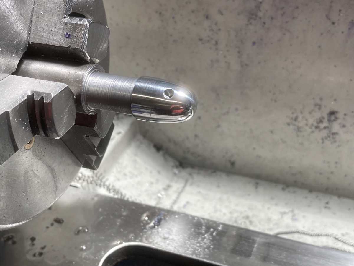
While it was all running true, I could tighten the nuts up onto the appropriate shoulder and finish the outside true to the shaft thread.
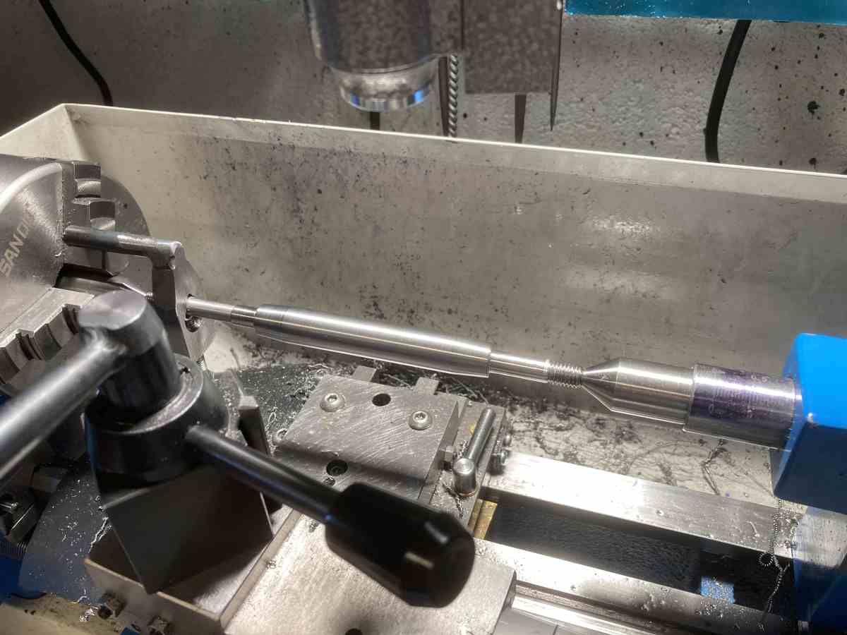
I hogged the rest of the shaft out 0.5mm over size then set it up between centres for finish turning (the first time I’ve turned anything between centres). There was about 0.05mm of runout in the shaft after roughing. When finished, there was about 0.004mm TIR which I was very pleased with.
I did cock it up though – I got both bearing journals to be a very good fit by lapping them to size, but when I was trying to finish the 7mm shaft through the compressor I ended up with it undersized and tapered.
I’d been hoping to achieve a slight shrink fit, so was looking to finish at somewhere around 7.005mm / 0.2758″ but ended up at 6.989mm / 0.2752″ at the outboard end and 6.972mm / 0.2745″ at the inboard end. I didn’t know how this had happened at the time (I’d noticed that the tool seemed to be producing more swarf than expected, but didn’t have the presence of mind to stop and check anything!
In hindsight, I believe that the shaft heated up and became too tight between the centres and started bowing – I had something similar happen when finish turning one of the tapers – I was checking the tailstock quite often, but not often enough, obviously! I think the long, slender section of shaft probably heated up more quickly than the thicker parts I had been working on at first and it caught me out.
The compressor wheel slid onto the shaft quite nicely, and I’d almost convinced myself it would be OK, but after sleeping on it (the problem, not the shaft!) decided that it wasn’t good enough.
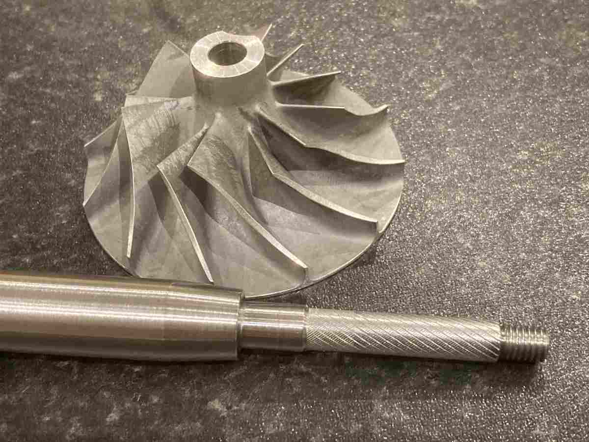
Not having either enough EN24T stock or the stomach to make another shaft, I thought I’d try and rescue this one by lightly knurling the undersized section and machining it back – if it didn’t work, I’d be ordering some more stock and making another shaft anyway.
This time, I managed to hit 7.007mm / 0.2758″ for the full length after lapping. As this isn’t a bearing surface, I’m reasonably happy with the result.
I lapped a bit of a lead onto the compressor shaft and the compressor wheel slides on about 6mm before meeting resistance. If I pour boiling water onto the wheel, it slides smoothly into position. When the wheel cools, it is absolutely rock solid on the shaft. More boiling water and it will slide right off again – very, very pleased with that!
I didn’t get a picture with it assembled at the time though!
There are a couple of spacers that need making, too. These need to be as parallel as possible. I ended up finishing one face, the bore and OD then parting off and turning an arbour to mount them on (with superglue ) to face them to length. Seemed to work OK – I made a couple of wonky ones, but on the good ones, I can’t measure any taper with a vernier micrometer.