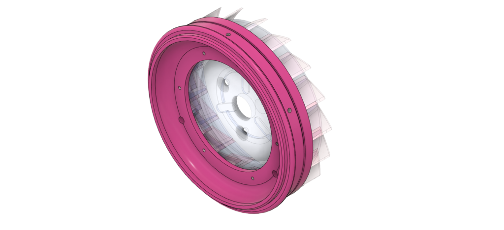
The book suggests machining the diffuser cover and intake from one piece – it would be a huge blank (about 120mm diameter x 60mm long), most of which would end up as swarf.
Making it in one piece also means that the compressor wheel and front spacer remain trapped inside the engine if the shaft is removed (the engine need to be dismantled release them). For these reasons (and others) I decided to make the diffuser cover and inlet as separate pieces.
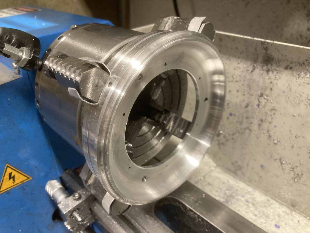
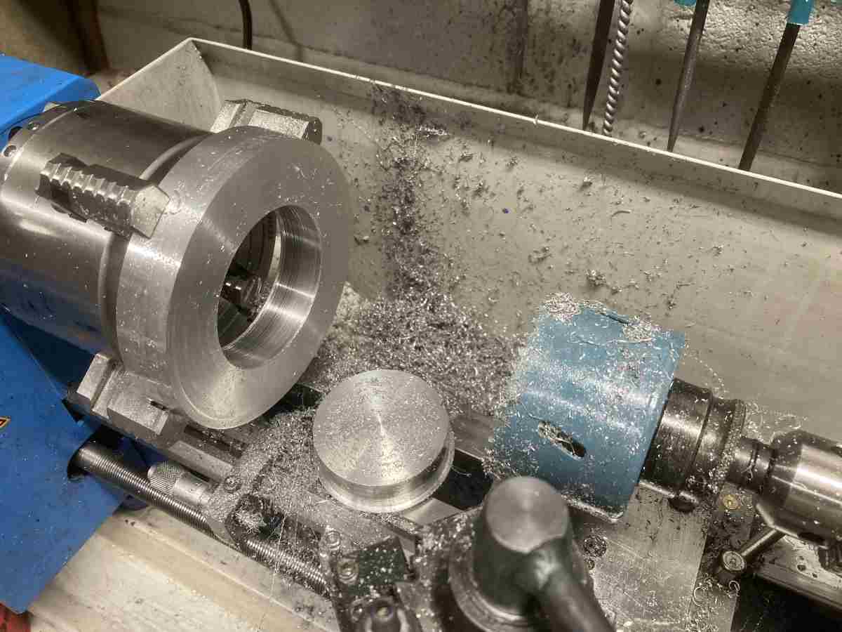
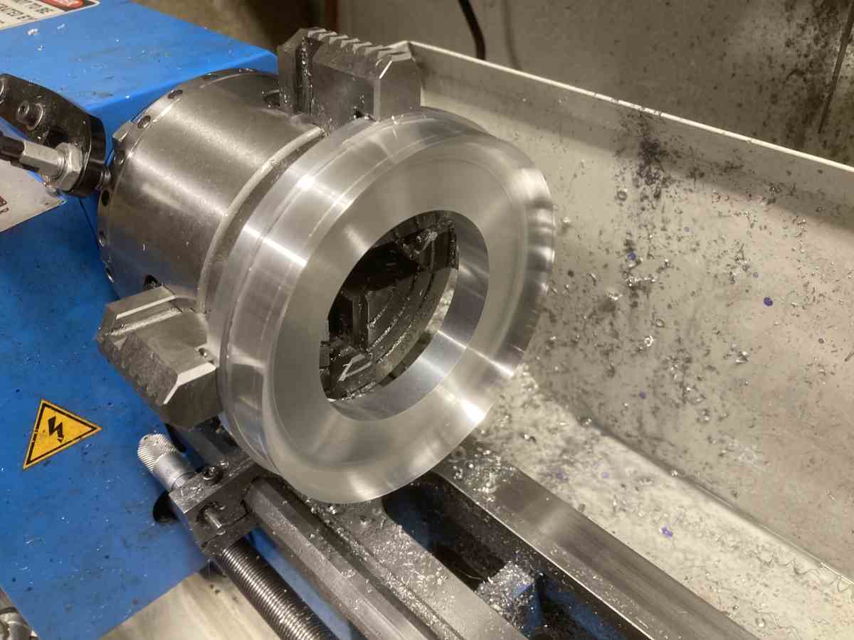
Because I’m stingy, I trepanned the centre out of the front cover with a hole saw. It made the lathe motor very hot!
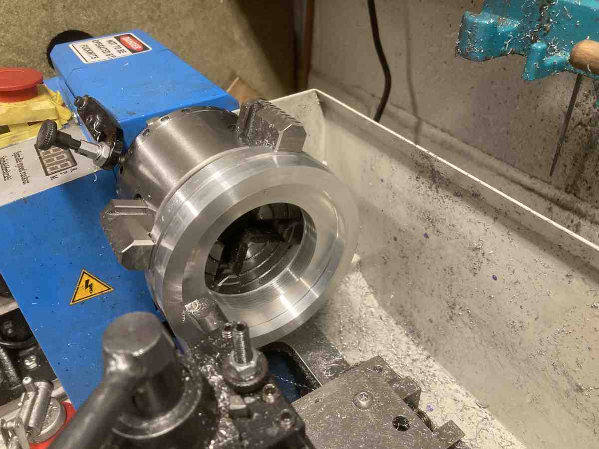
The central, flat section was bored out to leave a shoulder at the outer edge, where there will be a radius to match the outside of the diffuser vanes.
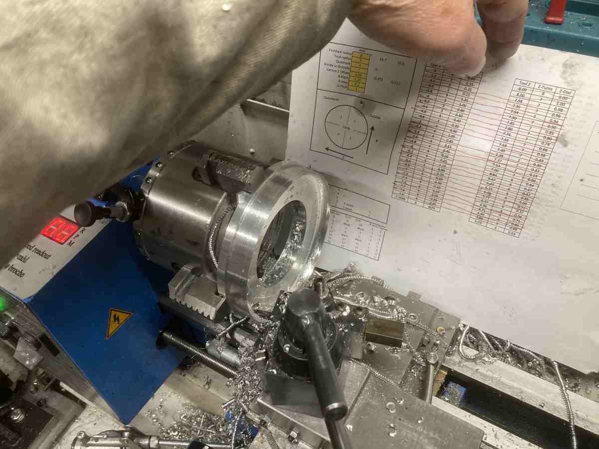
The radius at the outer edge was created by more ‘turning by numbers’
The diffuser fitted nicely against the resulting curve, and actually stayed put on its own.
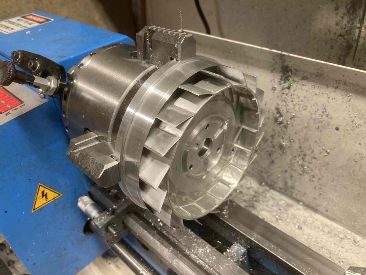
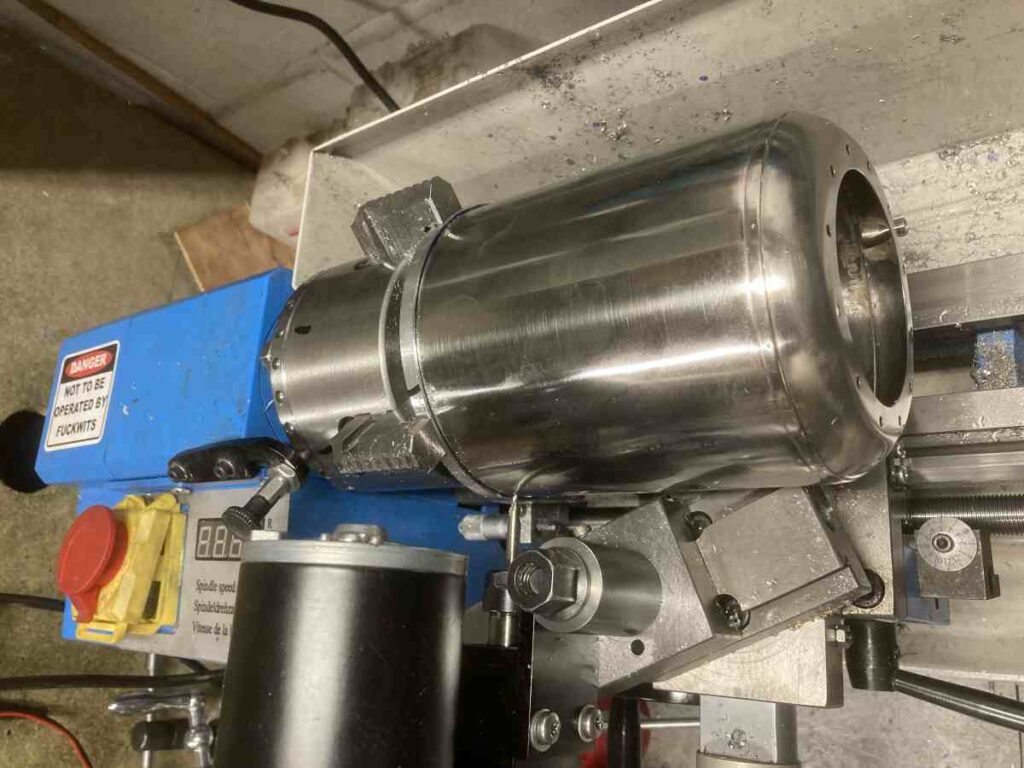
I could then gradually turn the OD down until the casing would just fit over it.
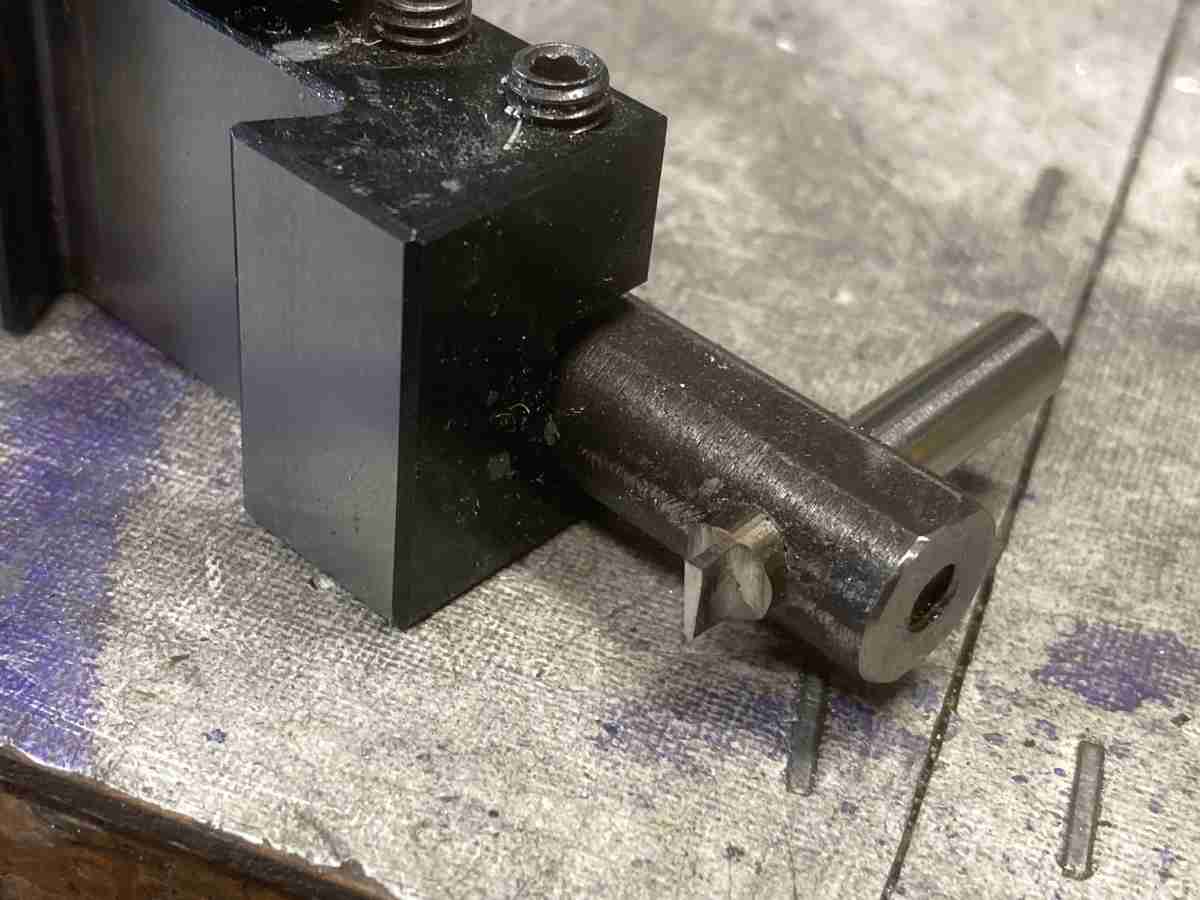
There’s an O-ring groove around the face but there’s not enough cross slide travel to get the toolpost outside the part, so I had to use a bodged together boring bar.
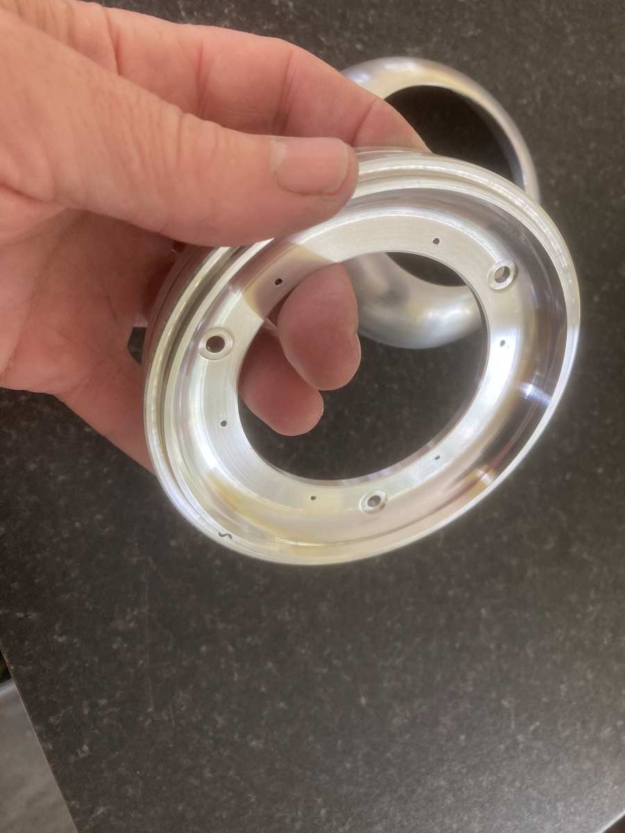
There was *just* enough clearance to get my toolpost spindle in to spot the holes for the securing screws in both parts if I contorted the top slide to just the right angle and used the last thread of its leadscrew (there was about 3mm total travel available on the cross slide).
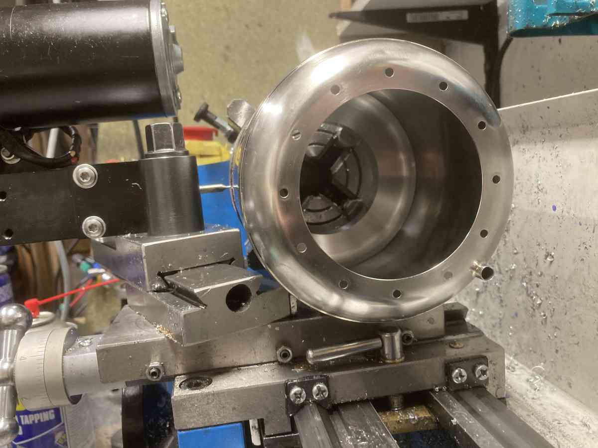
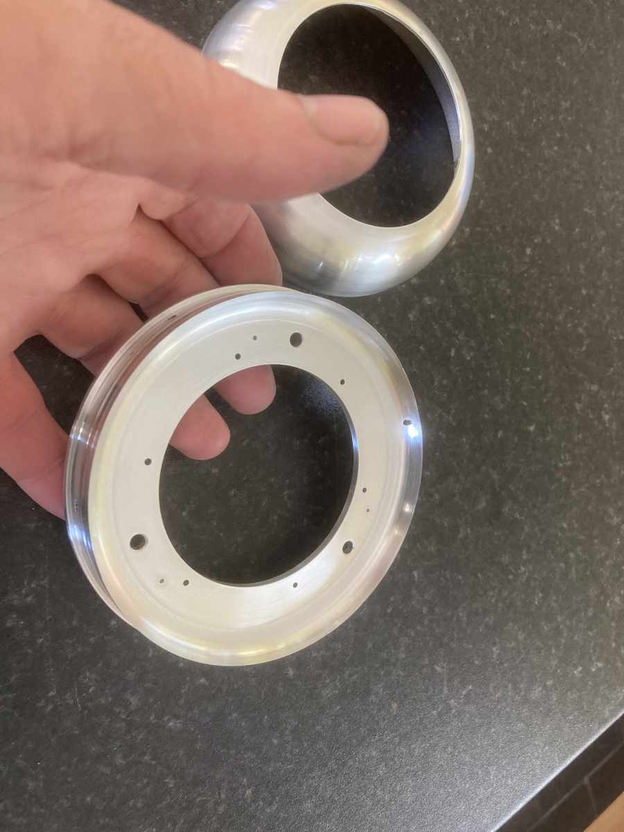
After drilling all the relevant holes, I reversed the part in the lathe and turned the front face, leaving a lip to suit my front fairing.