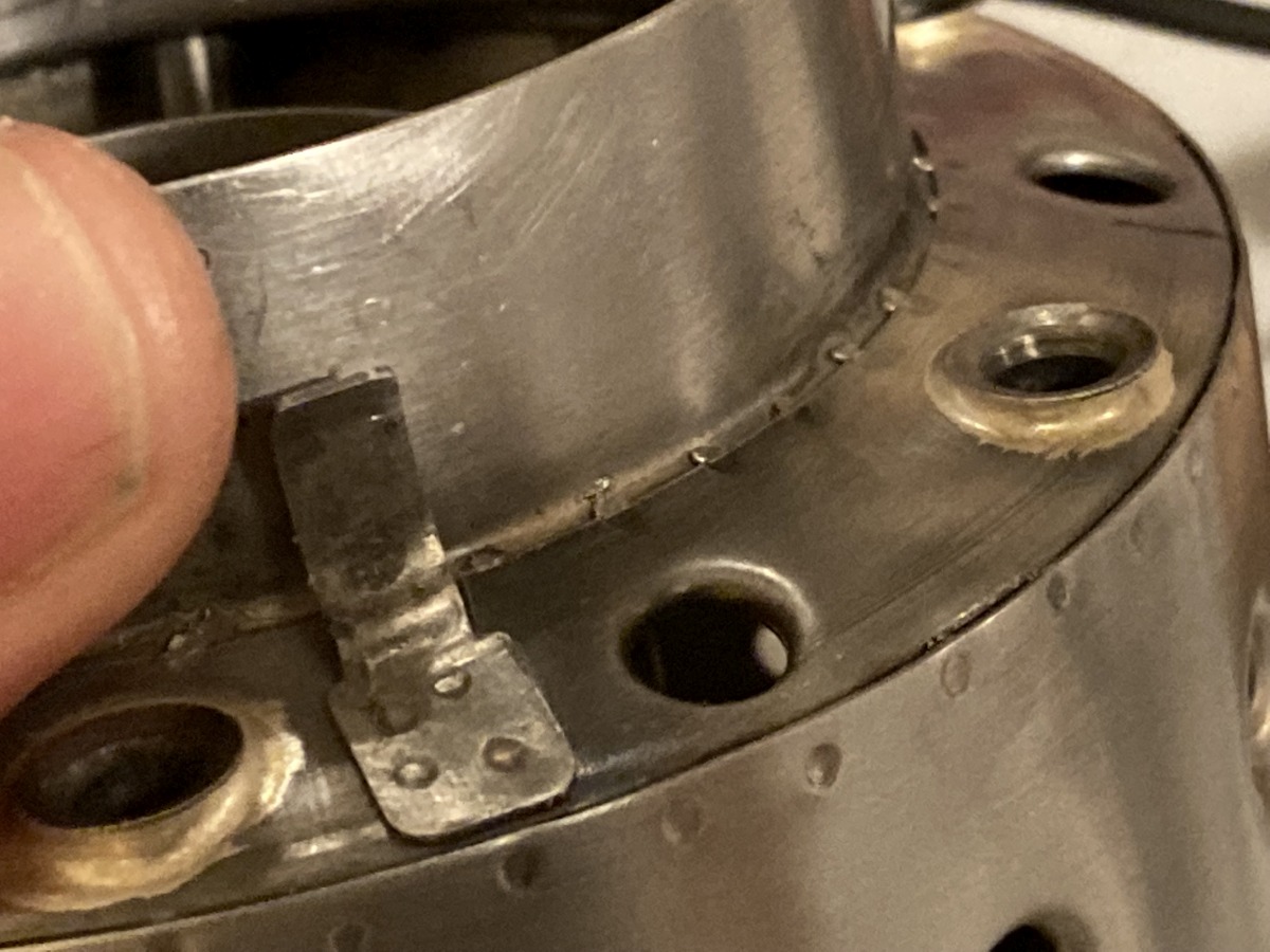
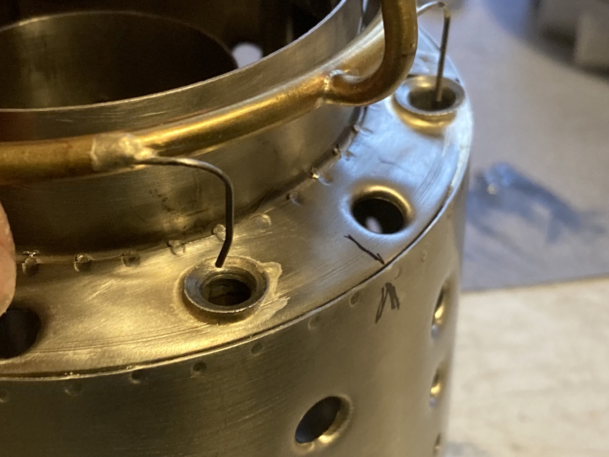
Once the outer casing was finished, I could make and fit the lugs that centre the combustion chamber within the casing to suit the actual casing ID.
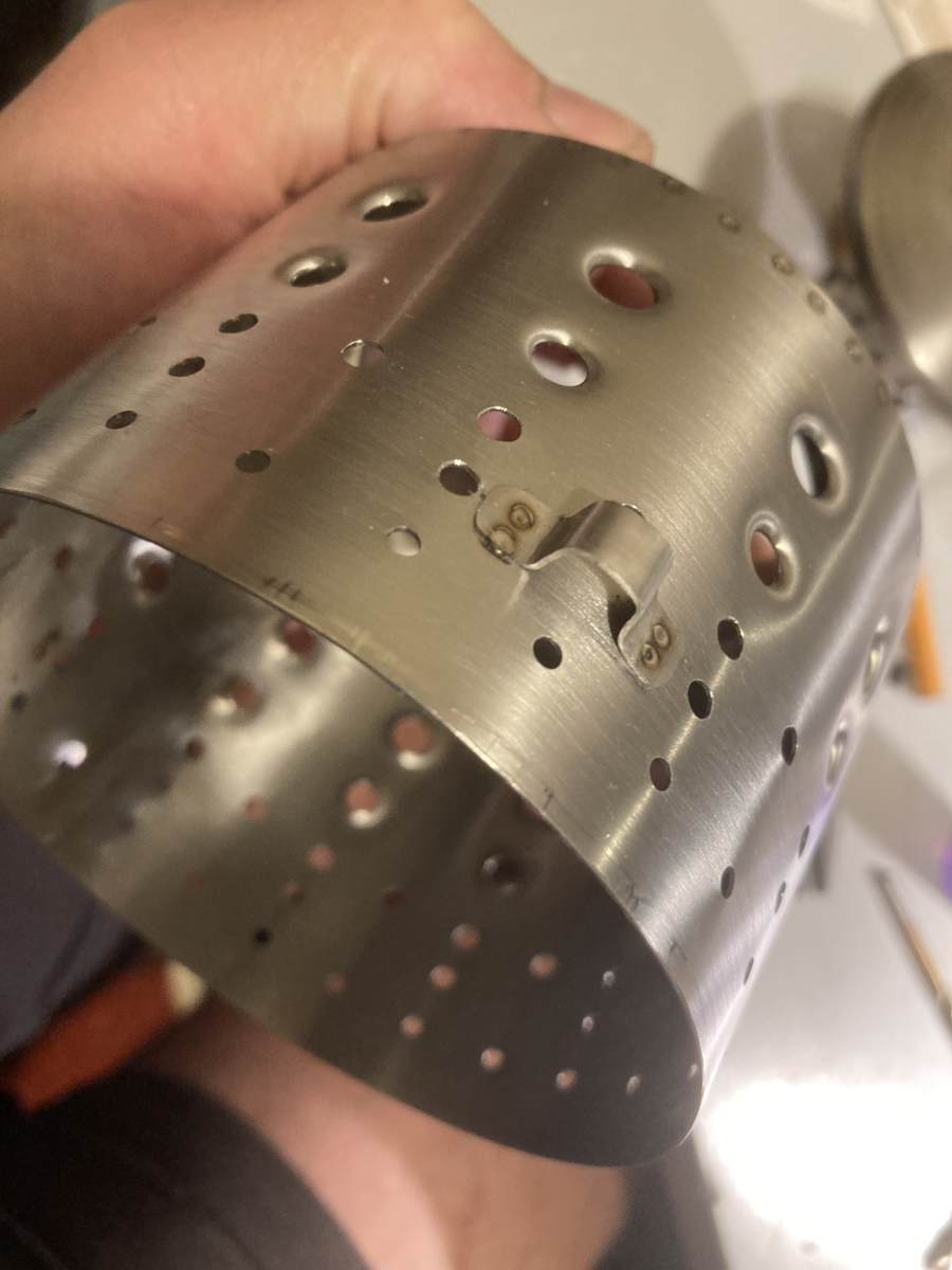
…And once the lugs were fitted, it meant I could silver solder the vaporiser tubes into place – apparently silver solder is OK here as the incoming air and liquid fuel keeps this end of the vaporiser tubes “cool”. (I couldn’t do this sooner, as I needed access inside the combustion chamber to be able to weld the lugs on.)
A wooden jig and wire was used to keep the front end of the tubes in the right place while the other end was soldered.
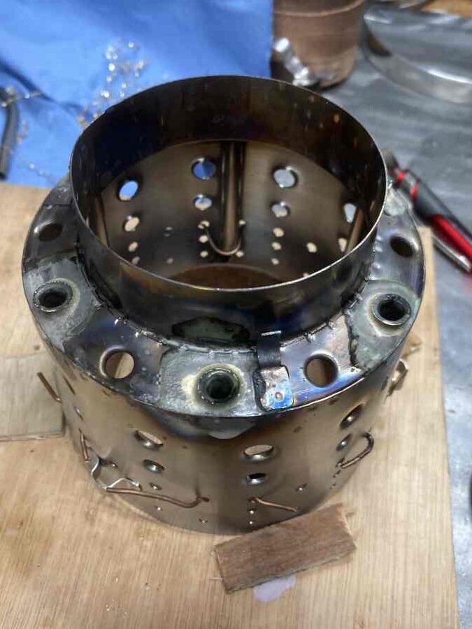
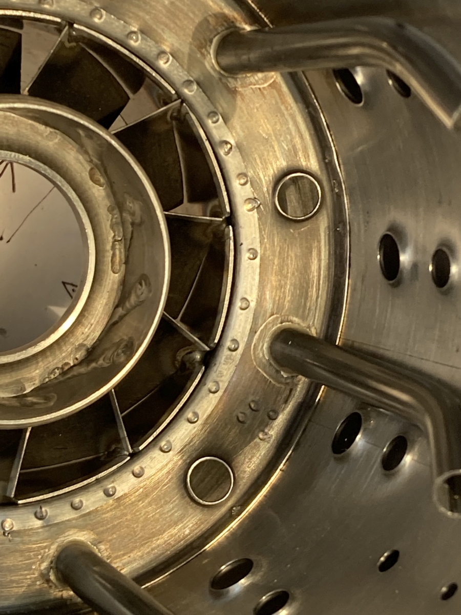
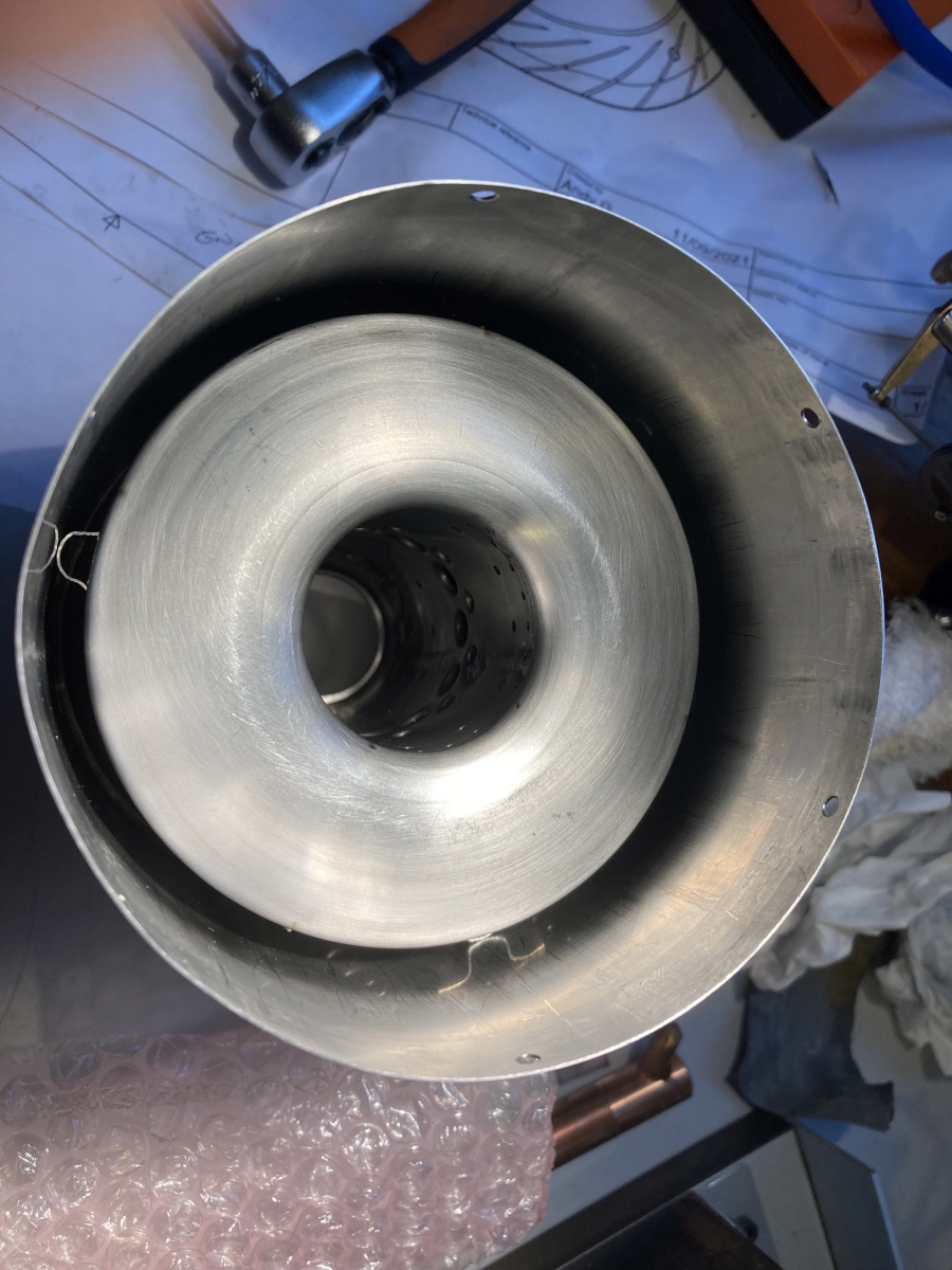
With that done, the two halves of the combustion chamber could be welded together together – This is the view of the exit from the combustion chamber towards the NGV before the front / inner went on (the gasses leave through the annular gap with the vanes in – the central hole is normally blocked by the shaft tunnel):
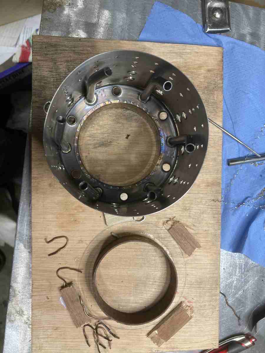
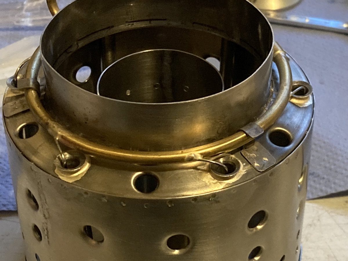
I smoothed out the chamfer on the front of the NGV and fettled some of the welds at the outside of the vanes before final assembly.
I decided to spot weld the two parts together on in the end (as a low risk option compared to tacking it with TIG). I had to make up a skinny lower arm for my spot welder to sneak through the gap between the inner and outer
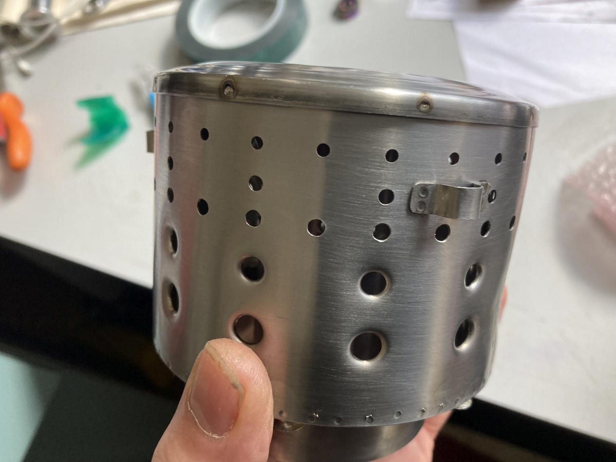
The combustion chamber fitted into the casing:
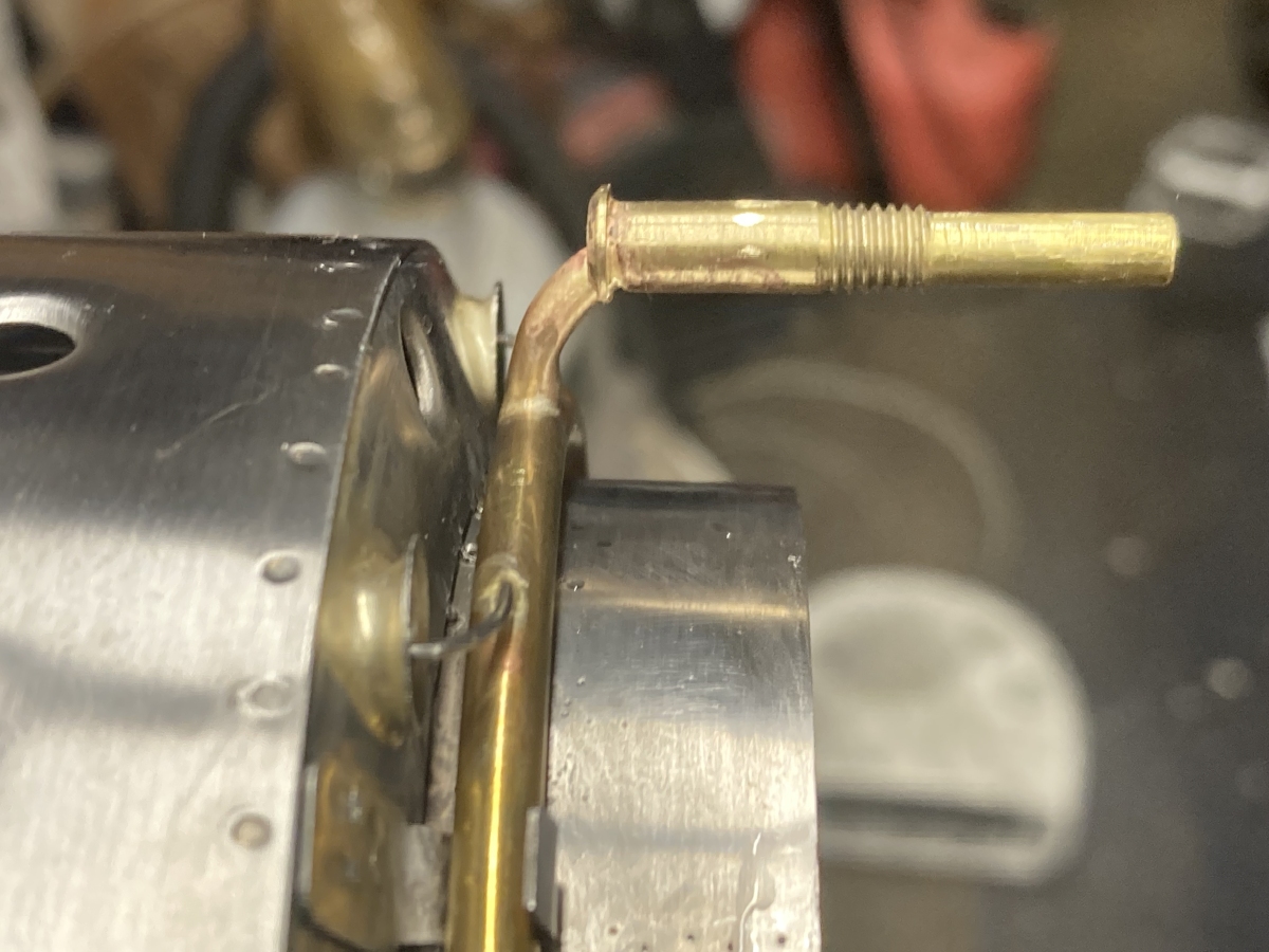
It slots around the NGV and is held in place by the fuel pipe being silver soldered into a threaded fitting that fits into the hole in the back of the casing. This is a minor PITA since the fitting has to be in just the right place to tighten up as the same time as the combustion chamber bottoms on the casing.
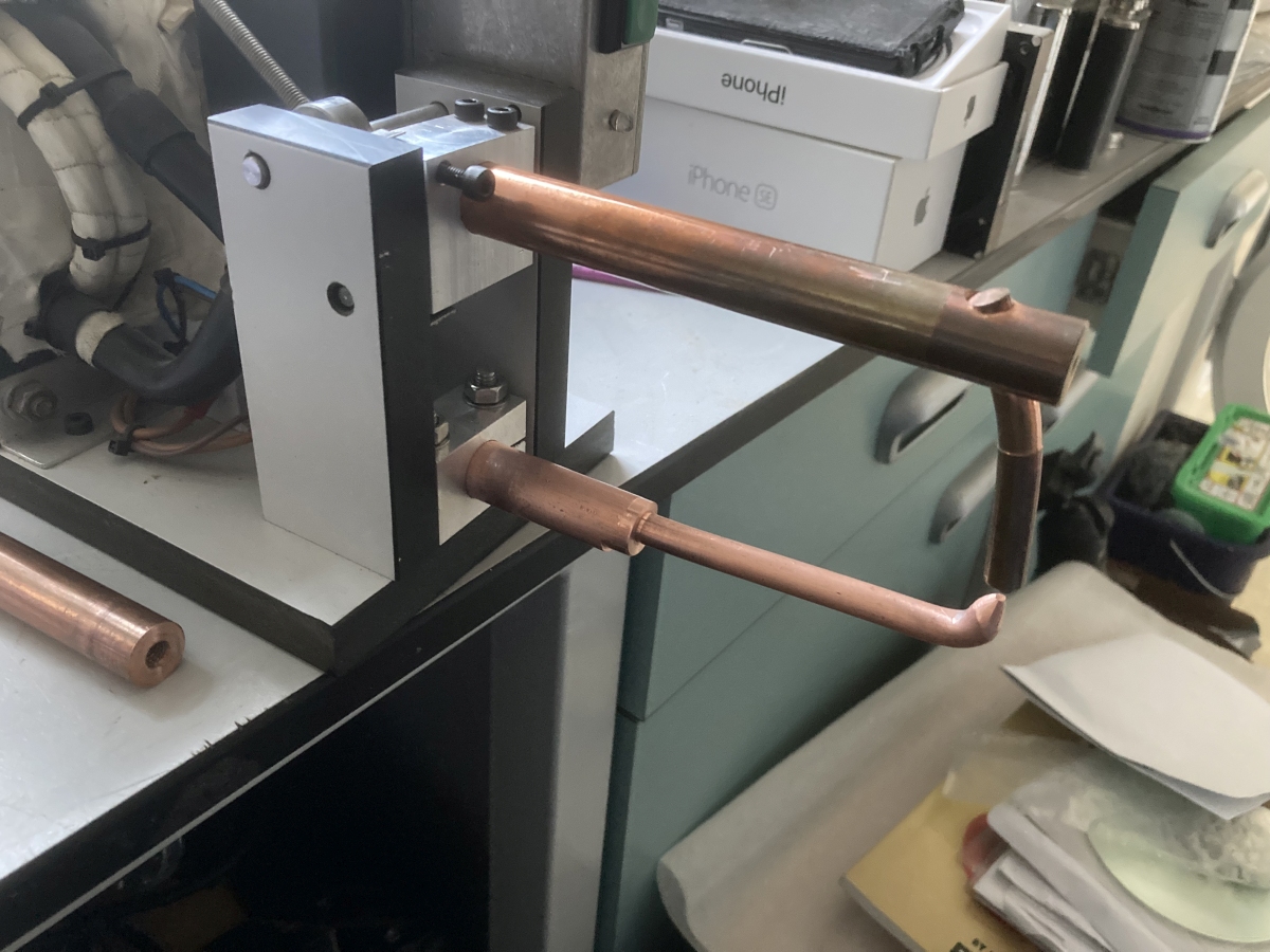
So I fitted the fuel manifold, putting a little tweak in the end of each needle to try and ensure the fuel washes the wall of the vaporiser tube, before locking the fuel manifold to the combustion chamber:
Then everything could be fitted loose and the NGV removed to see what clearance there was between the end of the combustion chamber and the casing. The fuel feed pipe was gradually shortened until the gap was closed:
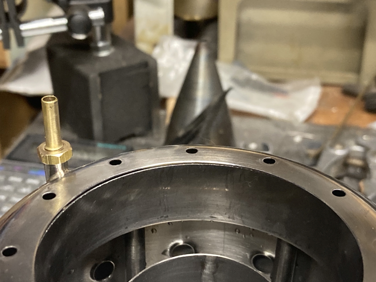
I’d made the fuel feed to come out of the manifold and bend around to go straight out of the back of the casing (as per the drawings in the book). This meant that the fitting needed to be almost on top of the bend, so a bit of fettling was needed. I’ve since noticed that one of the photos in the book shows the fuel feed pipe going forwards from the manifold and turning 180 degrees to come out of the back – I wish I’d noticed sooner as this would have given a lot more wiggle-room! (A lot of designs take the fuel feed out through the diffuser and front cover, but the thin, sheet metal, vanes of this diffuser mean that this would partially block the air flow.)