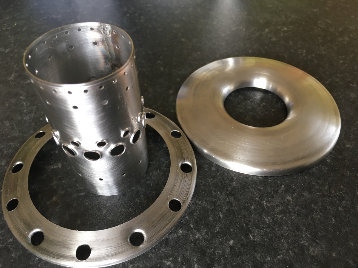
I made a start with the combustion chamber (the grey bit with the holes in). It’s supposed to look like this (mostly 0.5mm 304 stainless):
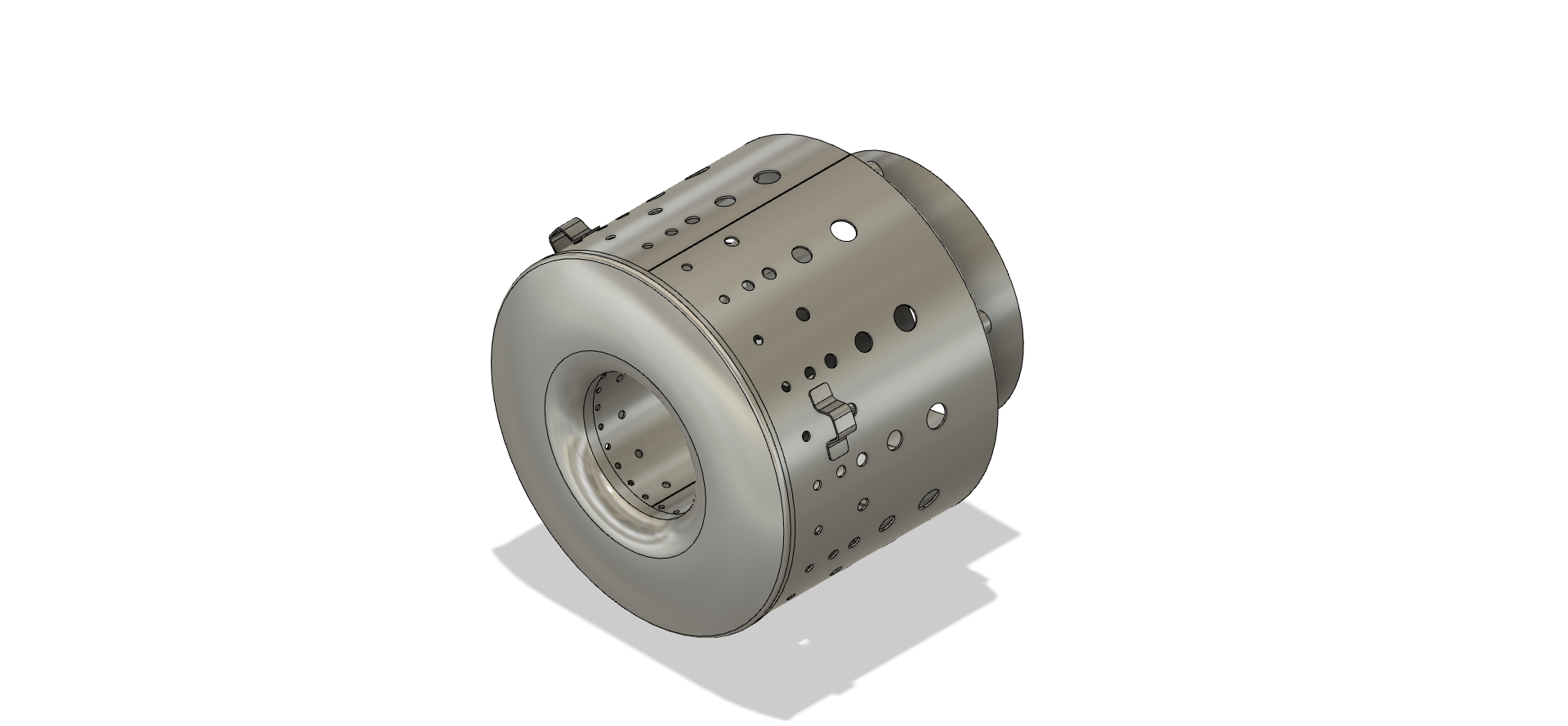
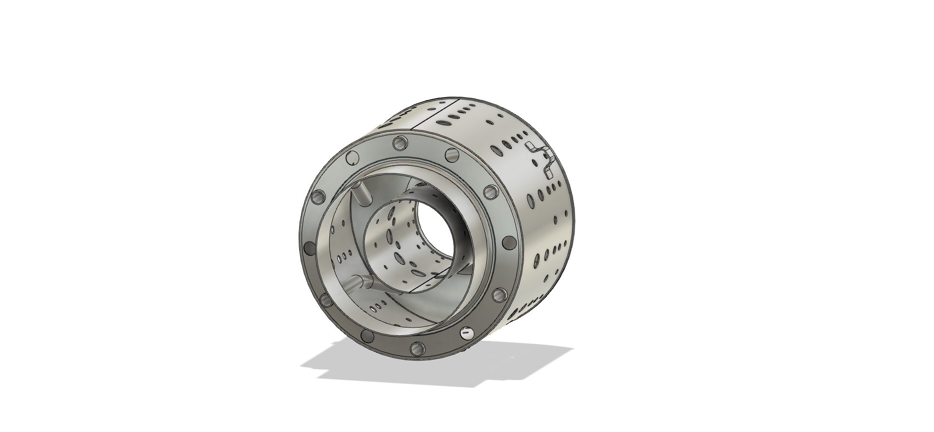
It acts a bit like a blowlamp nozzle – air gets fed from the outside and fuel gets fed to the inside (through the cranked vaporiser tubes) and the fire goes out the back.
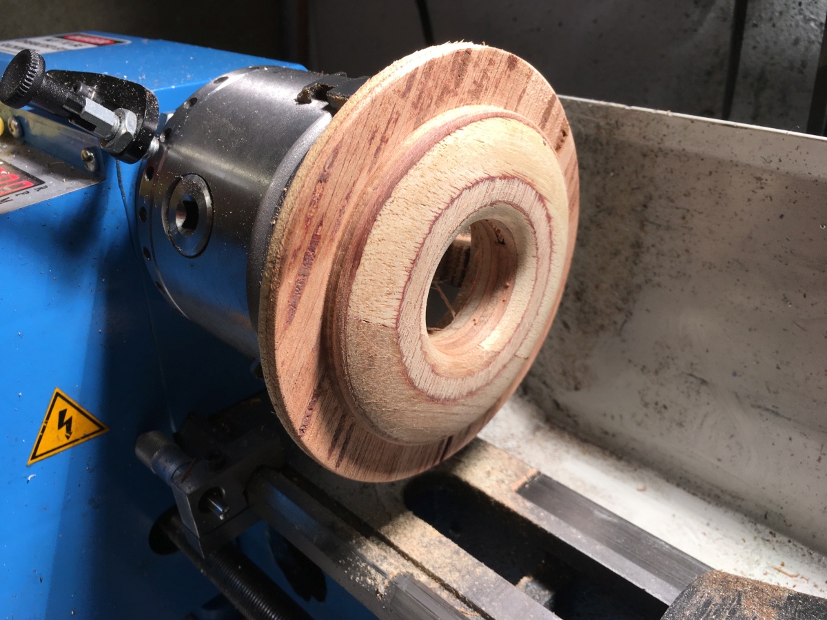
The front cover was spun over a plywood former on my mini lathe:
I formed most of the cover with a brass bar in the tool post of the lathe
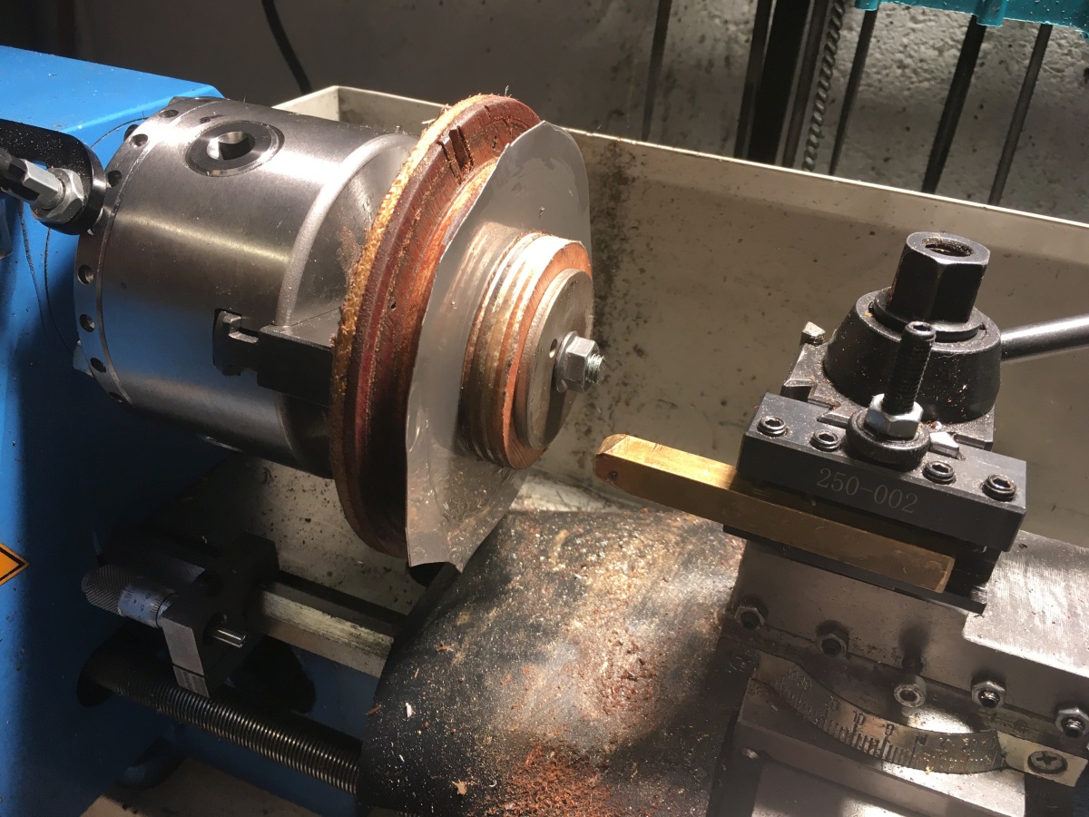
then used a bearing to tightly crimp the edge. I needed to remove the piece and anneal it to get the edge to turn down properly.
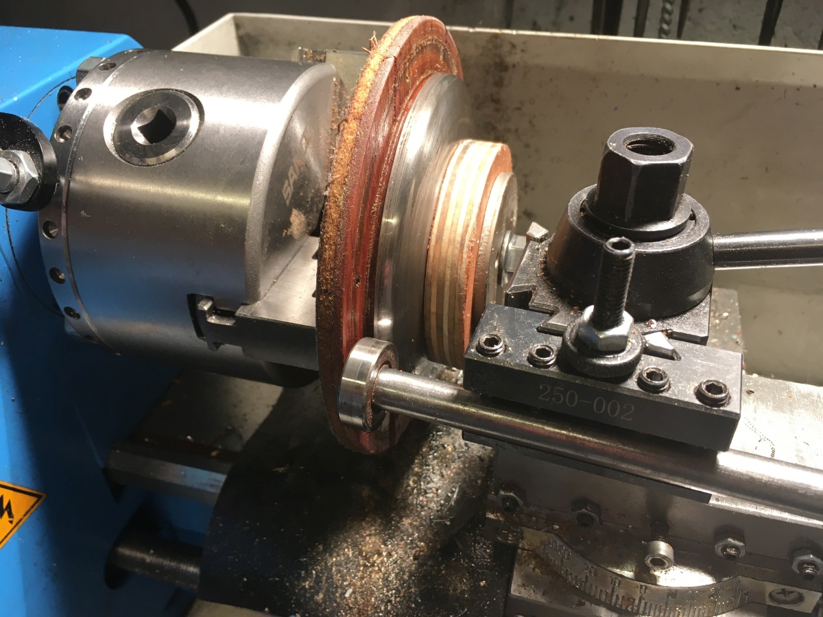
After this, I clamped the part over the outer diameter so that the centre clamp could be removed and used the brass bar again to form the central hole.
No photos of the inner hole being formed, but it was much easier than the OD and very pleasing to do!
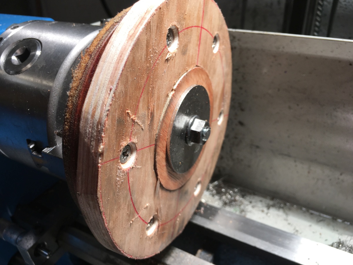
The rear cover was made using the same former and the holes drilled with a toolpost spindle while the part was still on the lathe.
The inner and outer walls of the combustion chamber have a pattern of holes drilled in them. I thought it would be difficult to weld the inner wall if I rolled it after drilling, even with a staggered seam, so I decided to roll and weld it first and drill after. I used the aluminium stock I had bought for the shaft tunnel as a mandrel to form the combustion chamber inner, shaving the diameter down gradually until I cold get the ends of the sheet to meet tightly.
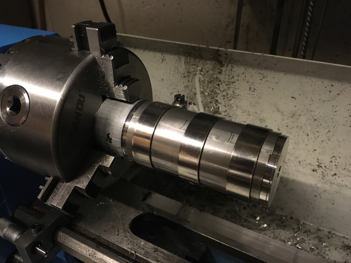
Then TIG welded the seam with it still on the mandrel;
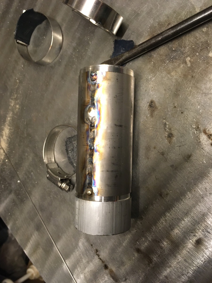
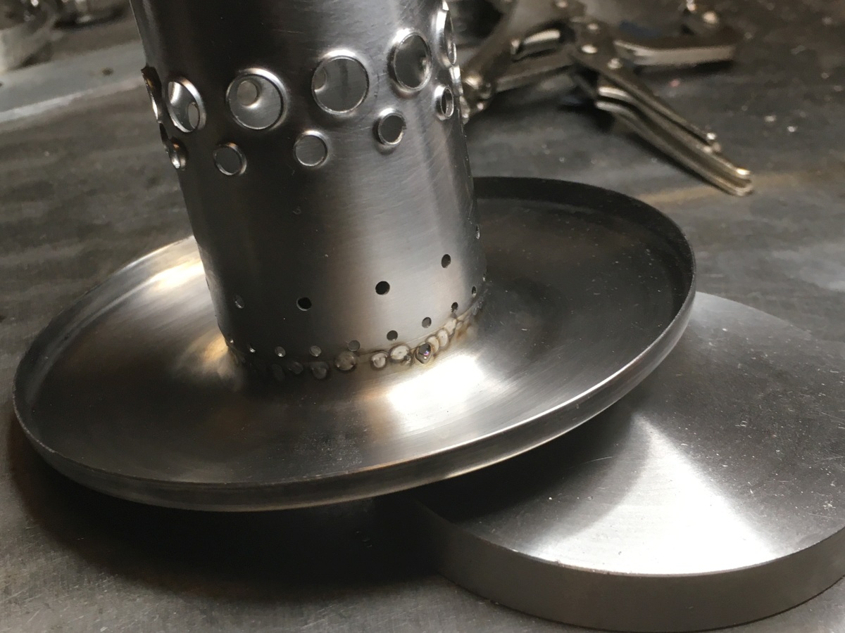
(A bit messy as I burned through in a couple of places and had to use filler rod to plug the hole, but it looked OK after grinding the tops off the lumps.
At this point, I could still move the inner.
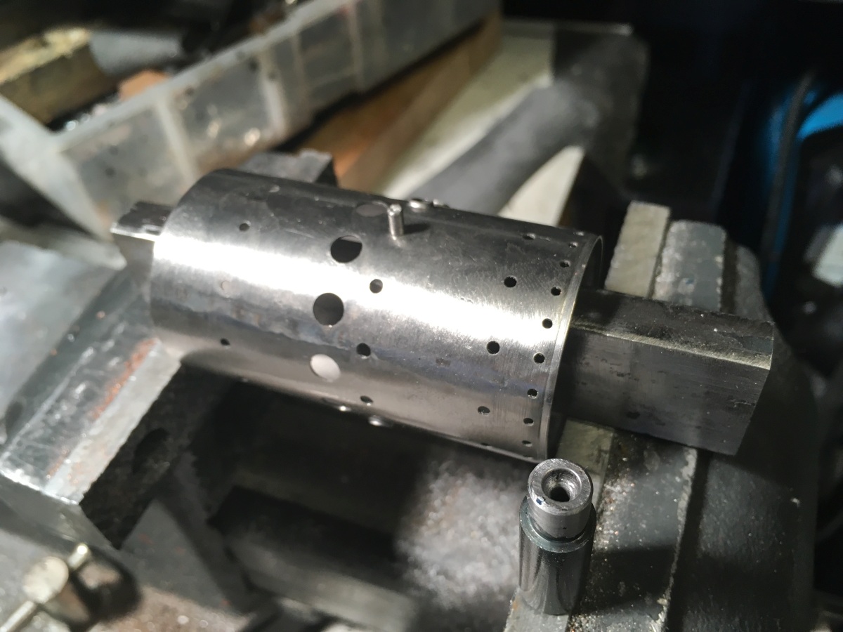
I parted the sleeve to length and decided I may as well drill the holes in the inner sleeve whilst it was still on the mandrel too.
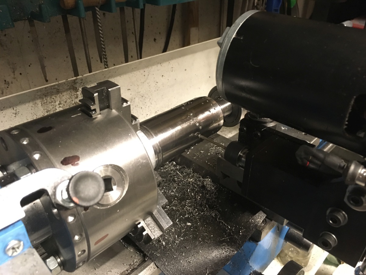
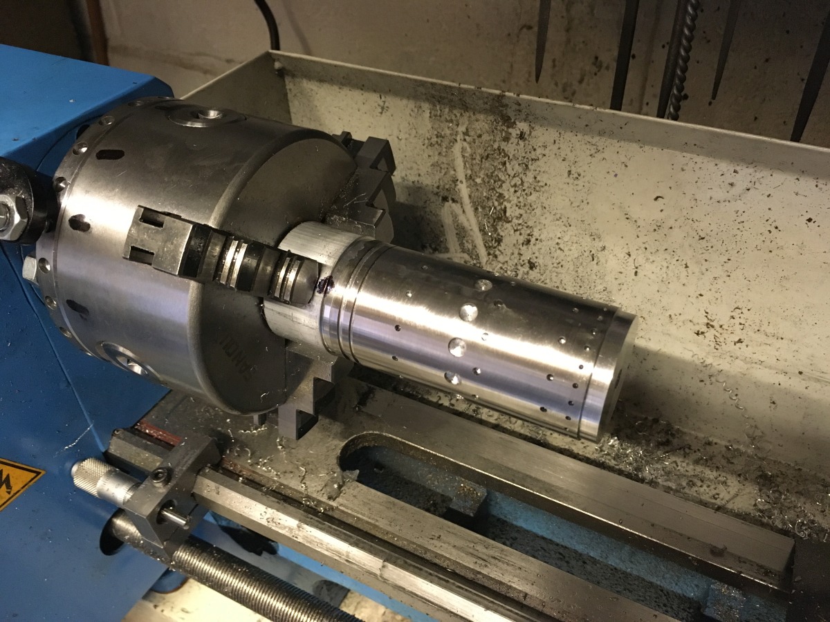
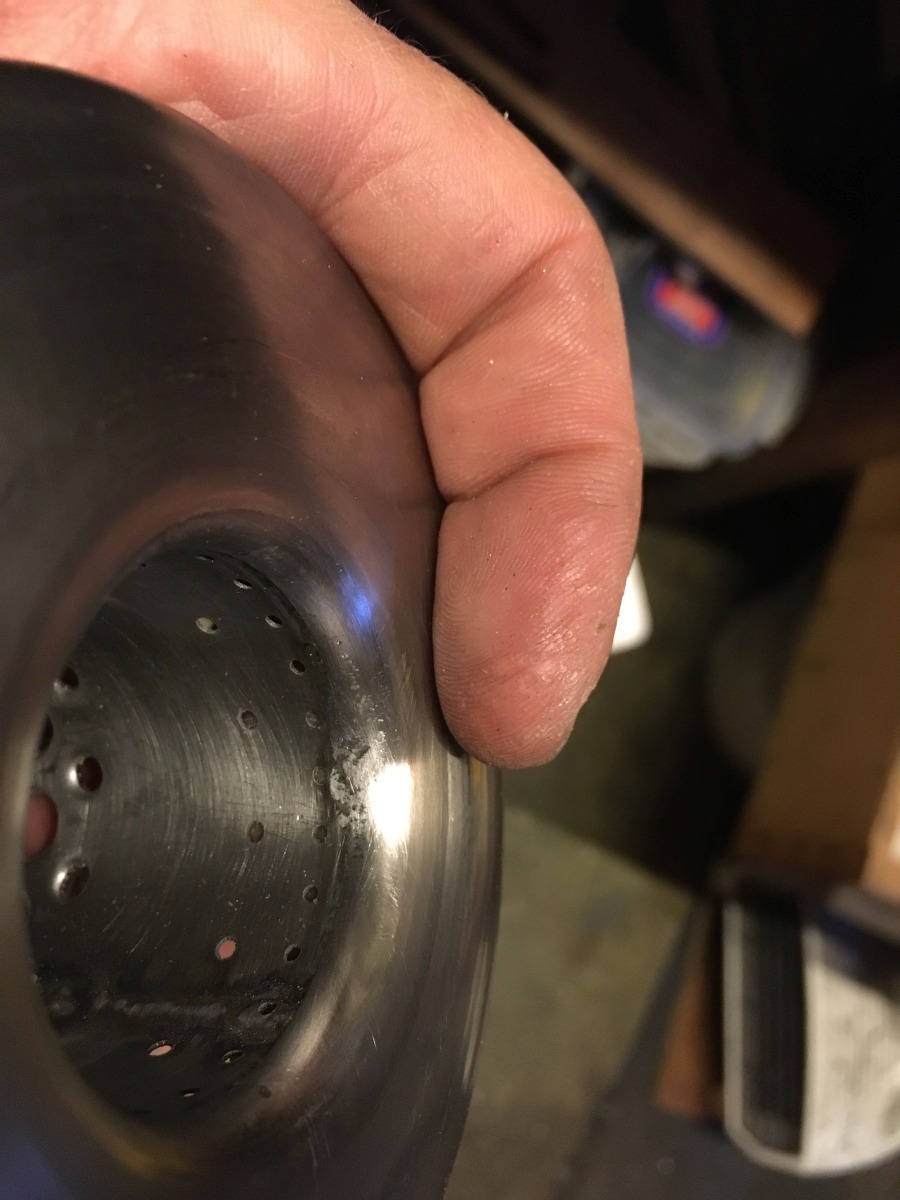
It turned out that it was a bit of a battle to get it off the mandrel! I thought I would be OK if I stuck the whole thing in the freezer (but I was wrong!)
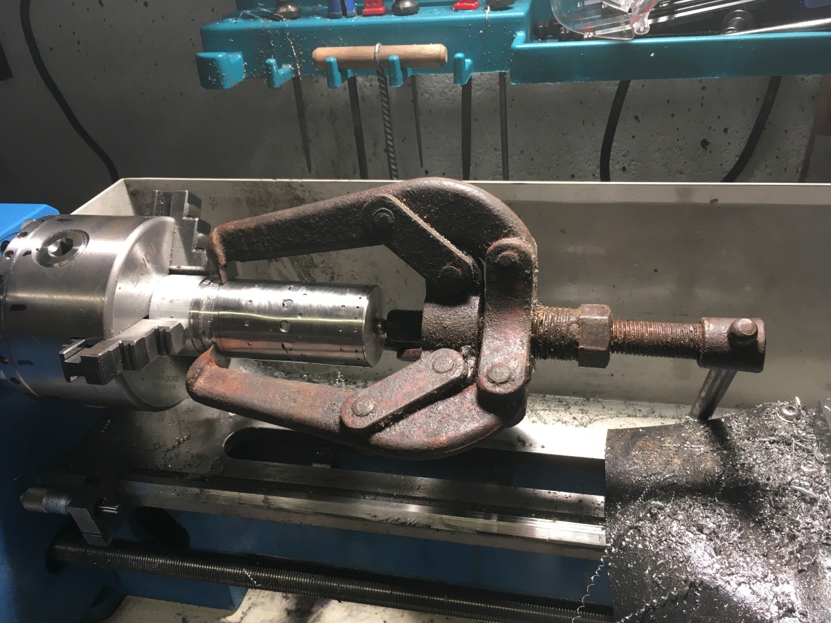
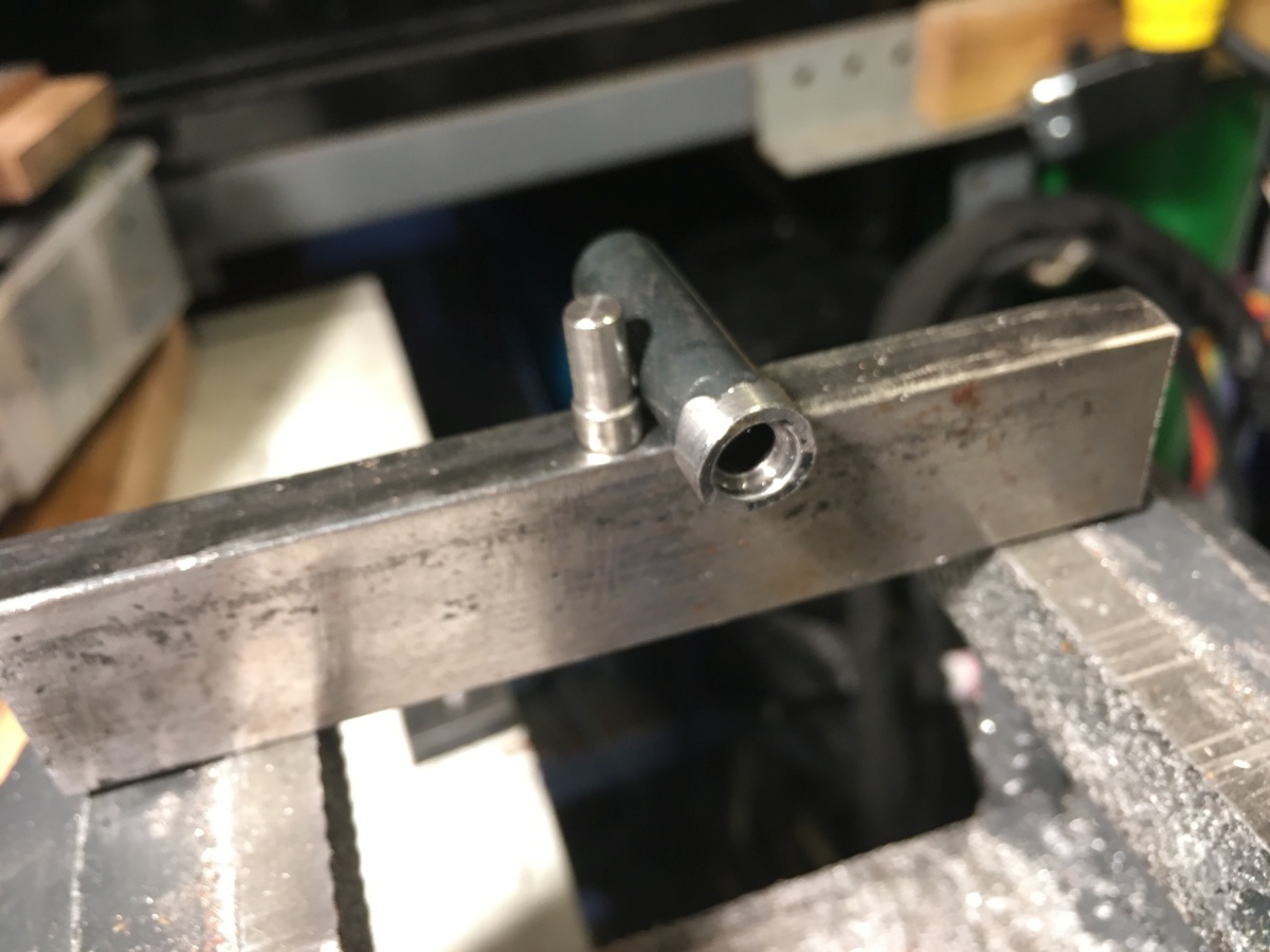
The design calls for some of the holes to be drilled undersize then swaged to the finished diameter, creating a sort of jet to direct the air into the combustion chamber. I swaged the holes in the inner wall using a punch mounted in a length of bar that fitted inside the tube and bridged the vice jaws. The die is made from a section of thick-wall pipe so that the surface matches the curvature of the combustor inner. It seemed like a good idea at the time, but not sure that it was worth the trouble compared to just turning the die with a flat face.
I was happy with this so far!
The inner and front were butt welded together with TIG spot welds. I only blew one hole through that needed a bit of filler rod to get rid of it.