
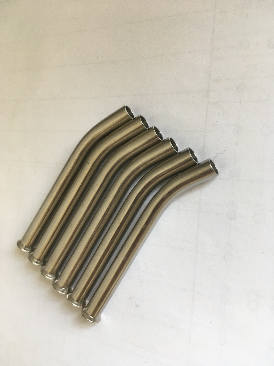
The other bits for the combustion chamber were the vaporiser tubes and the fuel manifold:
The vaporiser tubes are just 6mm diameter 316 tubing. Liquid kerosene is fed into them from injector pipes in the fuel manifold at the rear of the engine and emerges as vapour at the front of the combustion chamber where the fire is.
The ends were flared in the lathe (just using the tailstock centre):
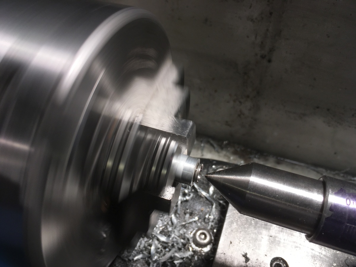
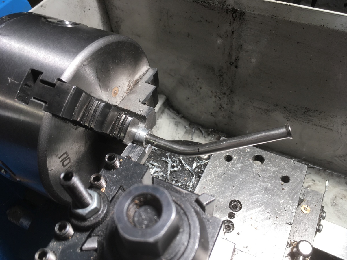
They are bent slightly – possibly to help impart swirl to the flame or possibly to make sure that the stream of fuel injected into the rear of the tube couldn’t spray straight through without hitting the tube at some point – maybe both.
…parted off to length…
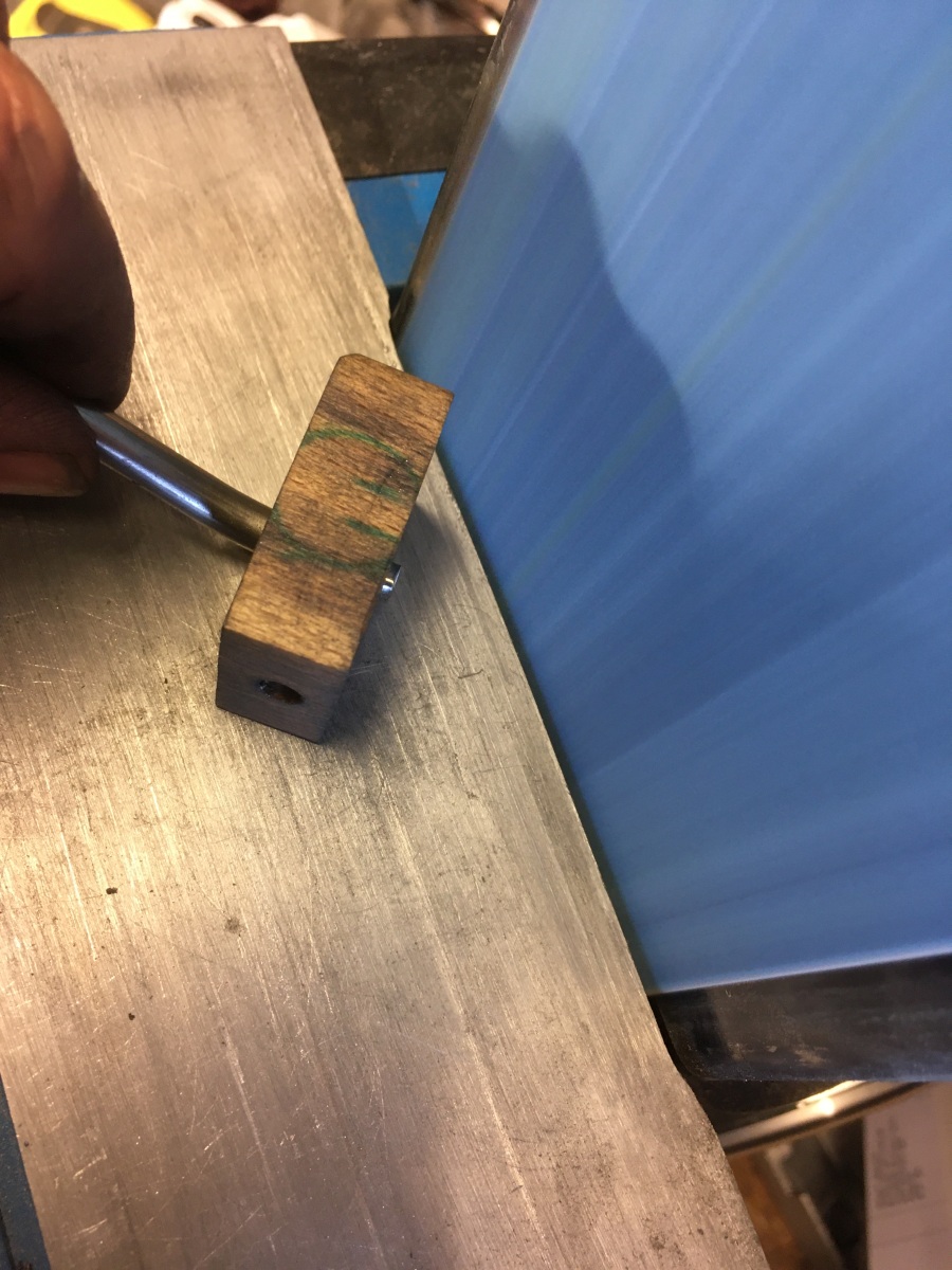
… and tidied up on the belt sander:
There are six vaporiser tubes in total
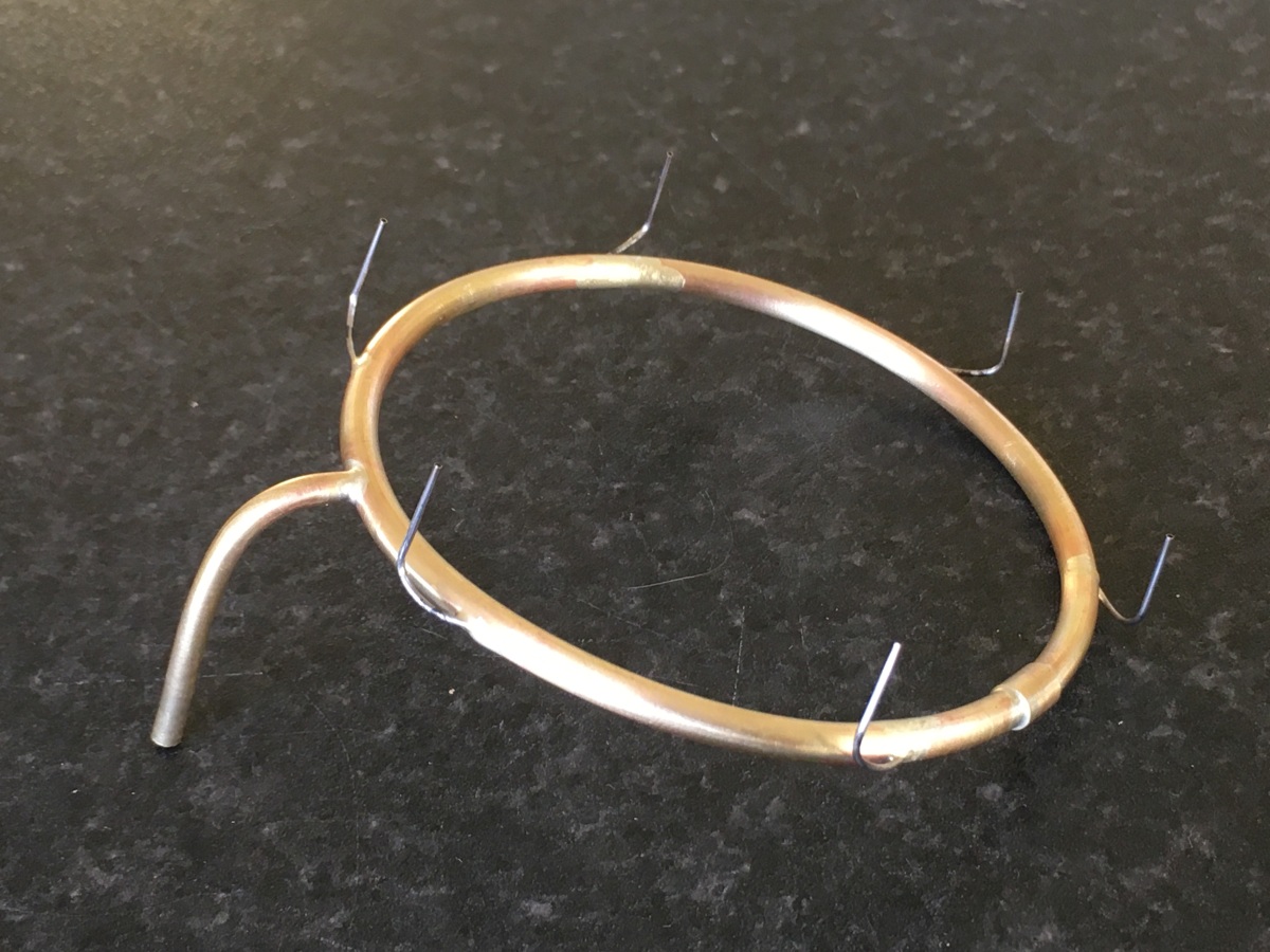
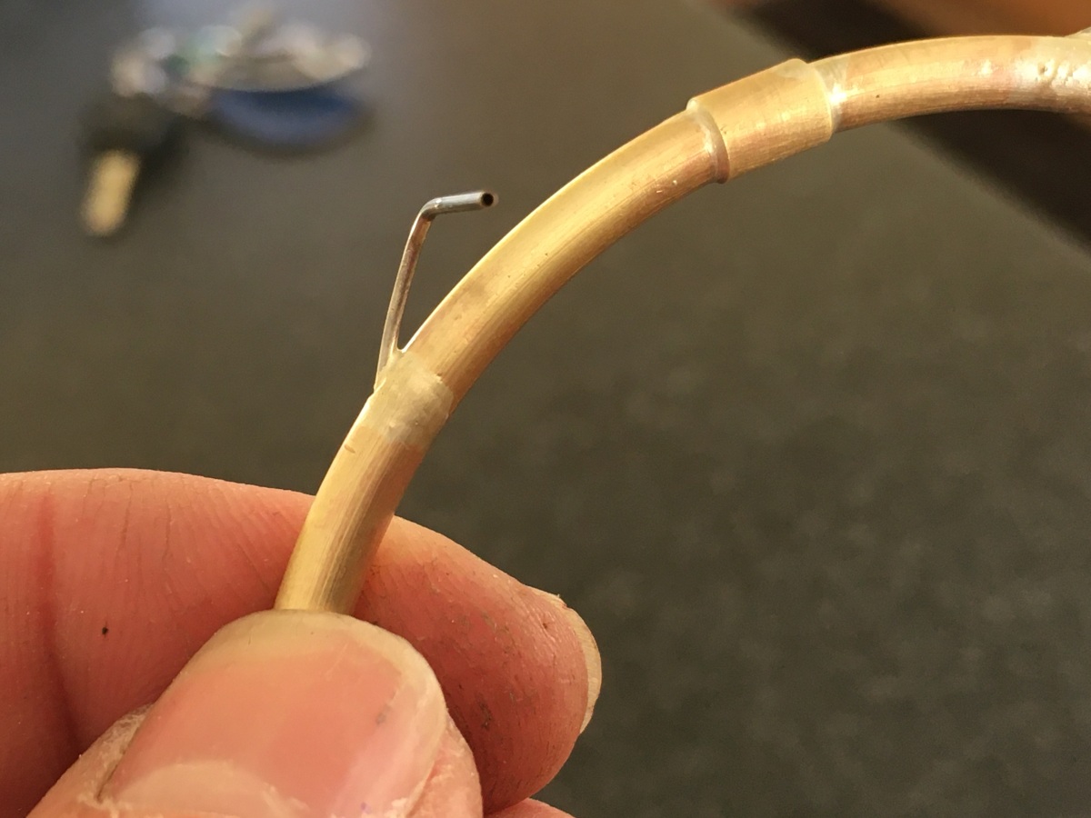
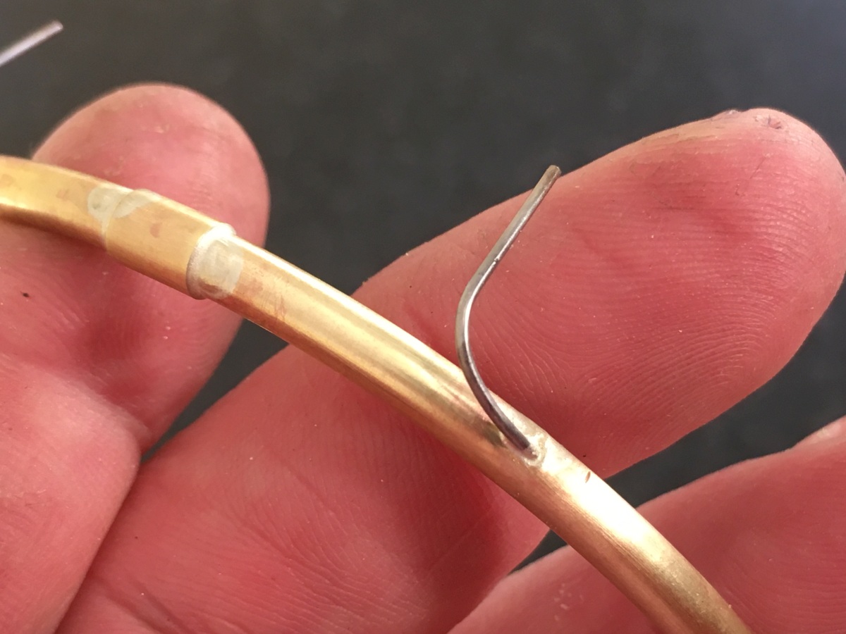
Fuel Manifold
The fuel manifold is brass tube with 0.8mm OD hypodermic needles silver soldered into it. Most of the length of the needle is threaded inside the brass ring – the needles act as restrictors to try and ensure and equal flow of fuel from each one:
It gets checked for leaks (with gas and a match – obvs.) and for uniformity of flow by connecting a temporary gas supply and checking that the flames from each injector are equal height.
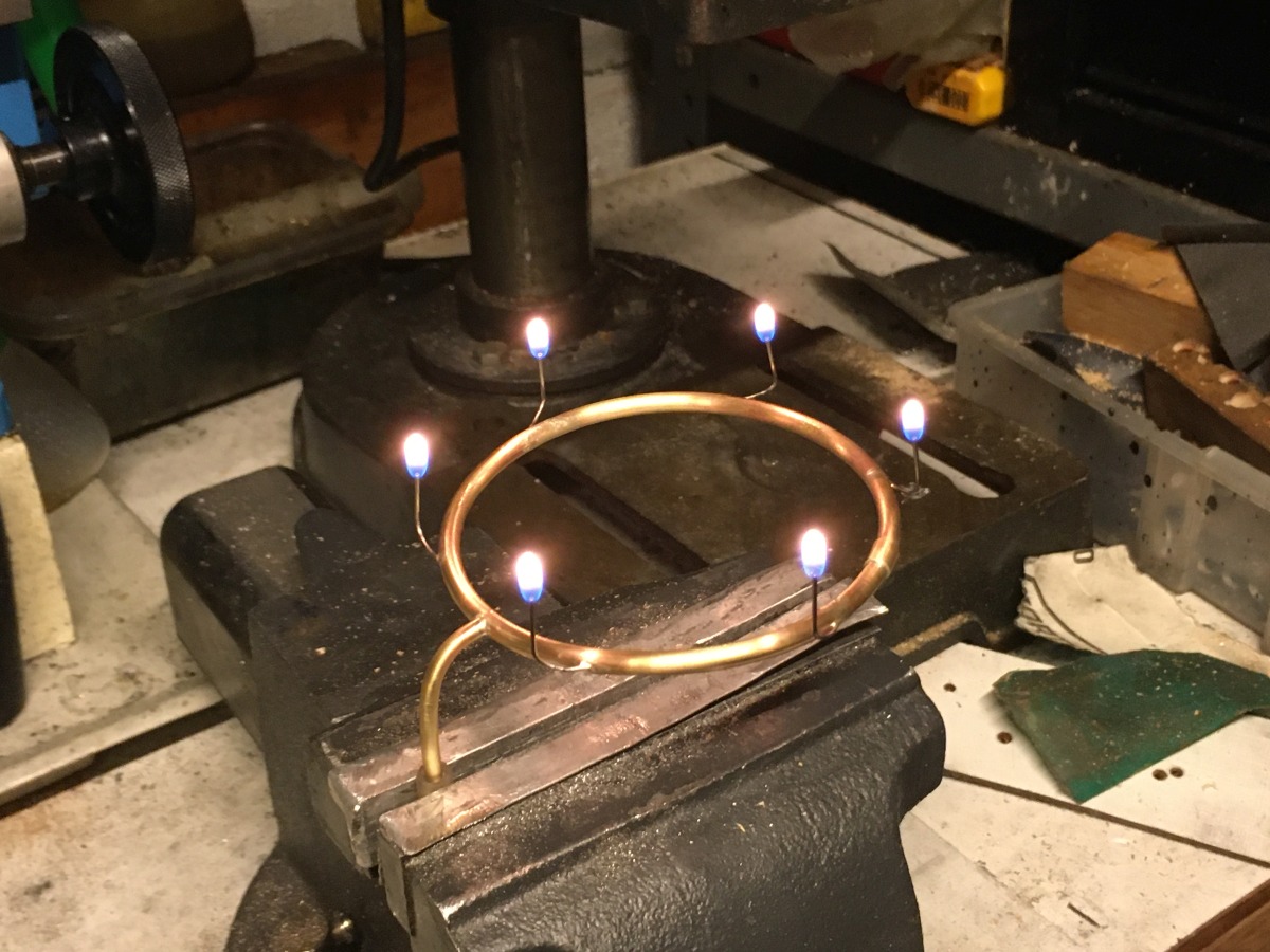
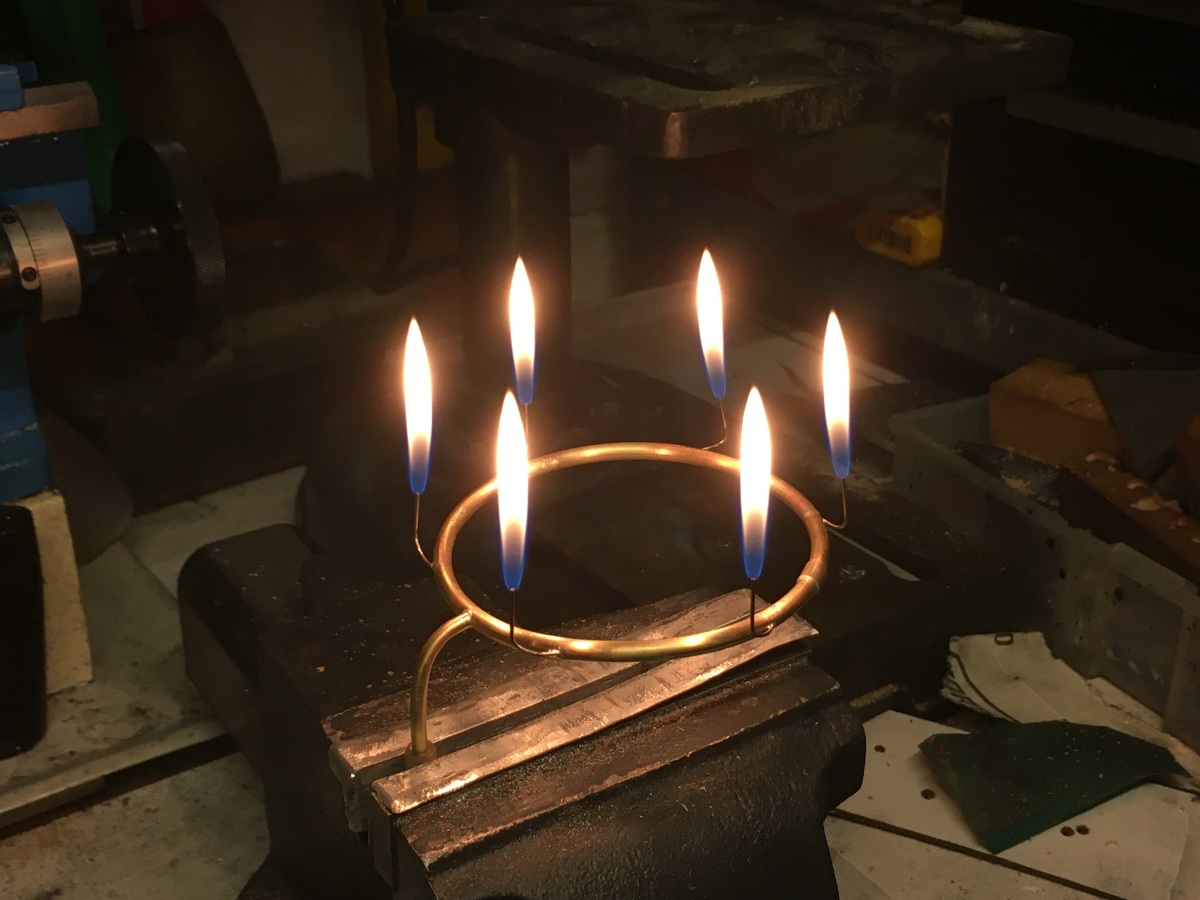
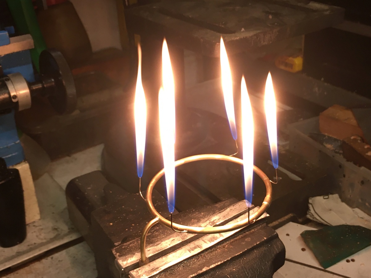
It looked OK to me.
Since I like playing with fire, I made a little video 🙂