
The tail cone is supposed to increase the thrust of the engine by managing the gasses coming through the turbine blades. The engine will run without it (sometimes better than with it) but I wanted to get it made so I could call the engine finished. It’s the sort of thing that people tune and play with to get the best performance from the engine, but knowing very little, and wanting to start somewhere, I’ve gone with the one in the book.
Inner Cone
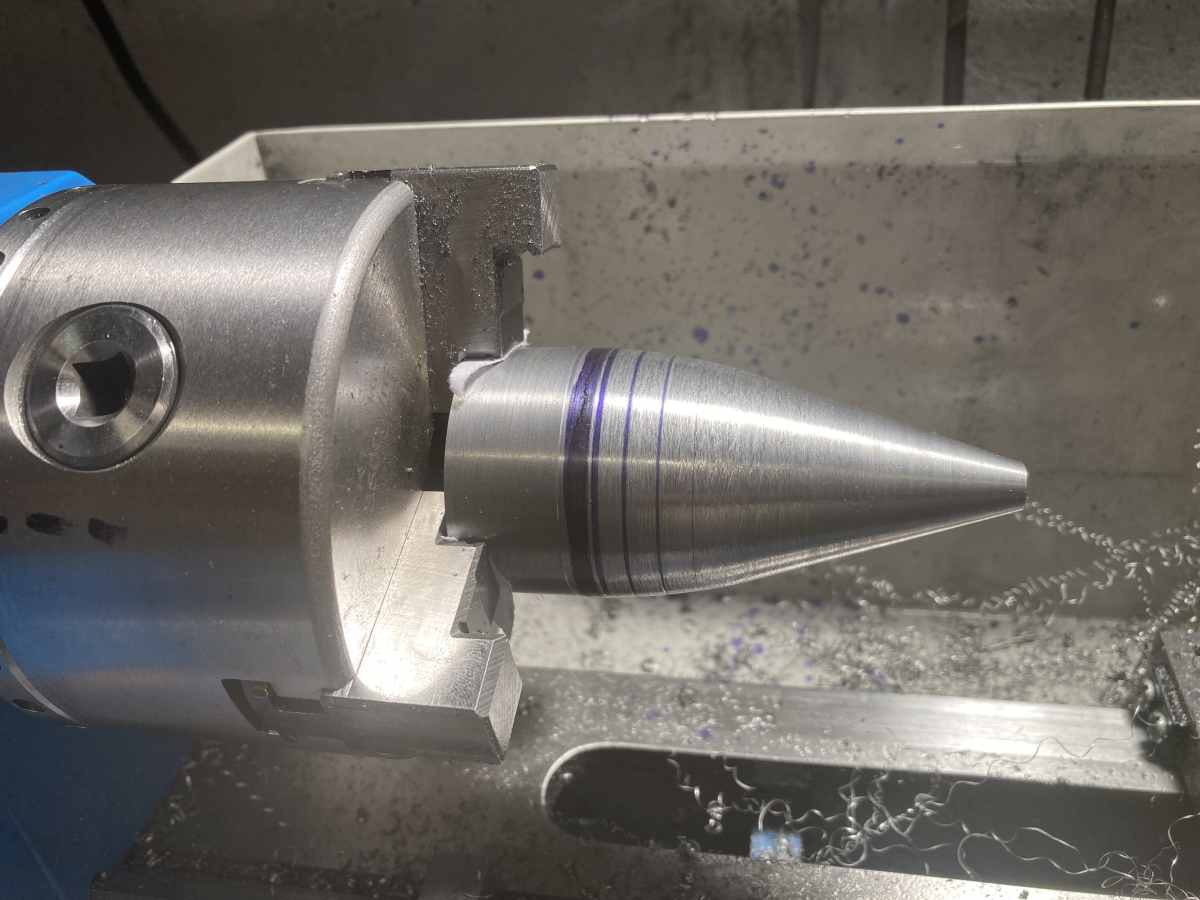
The inner part is a cone that transitions to a parallel section via a radius. The larger diameter should match the root diameter of the turbine blades.
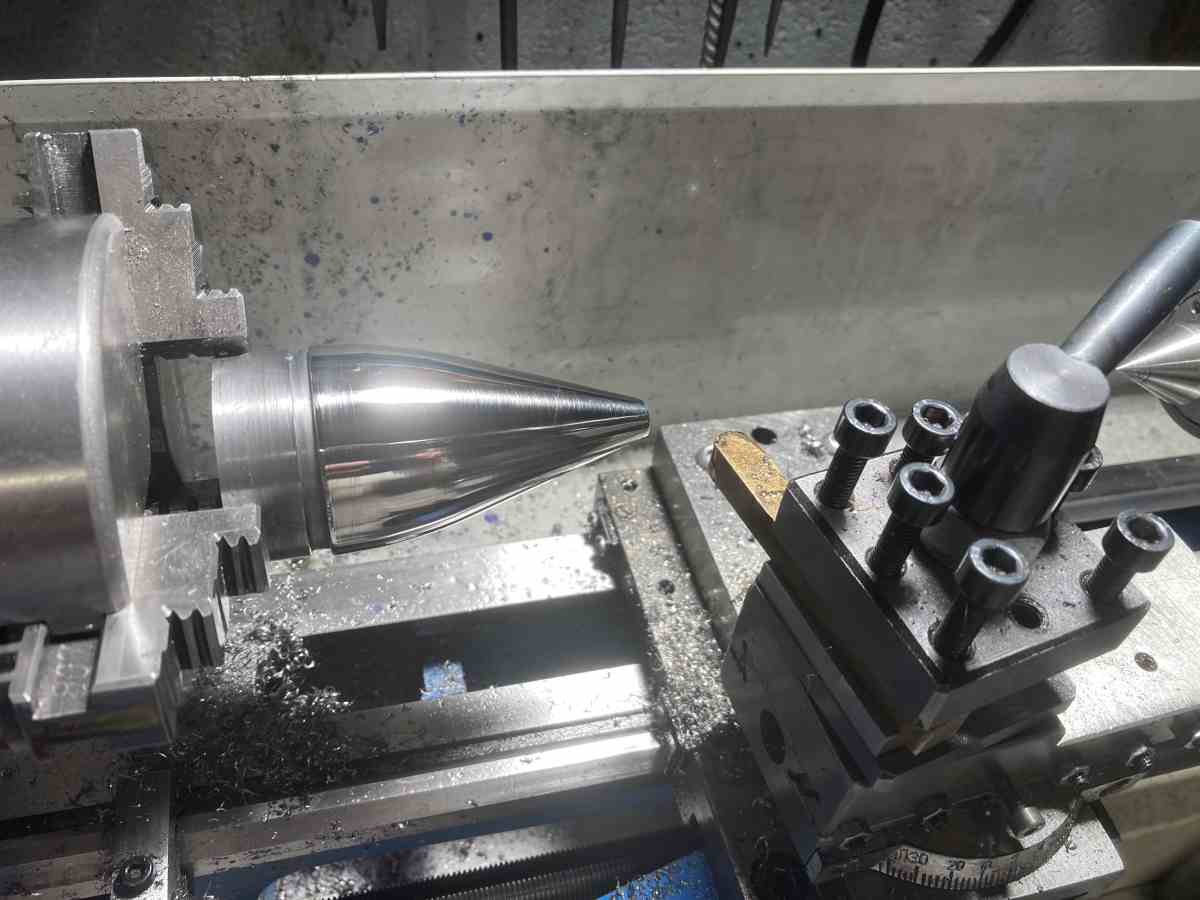
I turned a mandrel to suit the ID by machining the conical part, then a series of steps at known positions / diameters through the radiussed section. These were roughly blended by turning a series of tapers (judged by eye), before finally blending with a file.
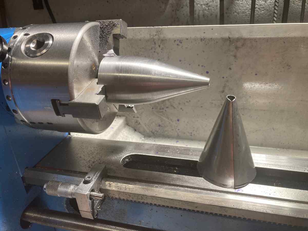
This is almost done – the blue rings are the remains of the layout fluid at the reference diameters
A few minutes with a file cleaned the mandrel up. Next to it is the rolled up cone that will form the blank (0.5mm 304 stainless).
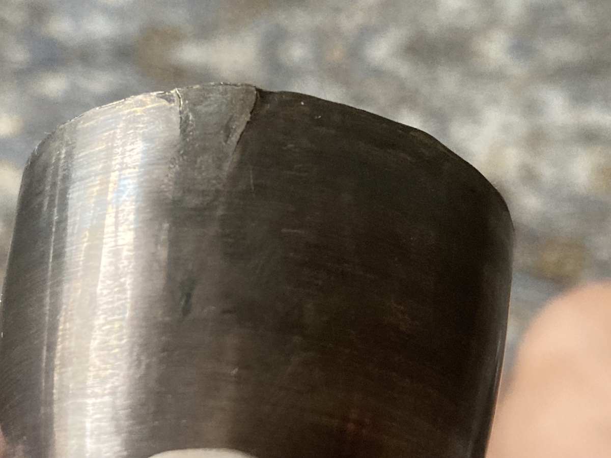
The welded blank and the mandrel. The blank is over length, so I will be able to cut the end with the missing weld off.

It’s actually the second one, as the first one cracked at the weld when I tried to spin it. I had used filler on the weld (to try and stop it burning back at the end) and needed to dress it flat, but I thinned the material out too much, I think.
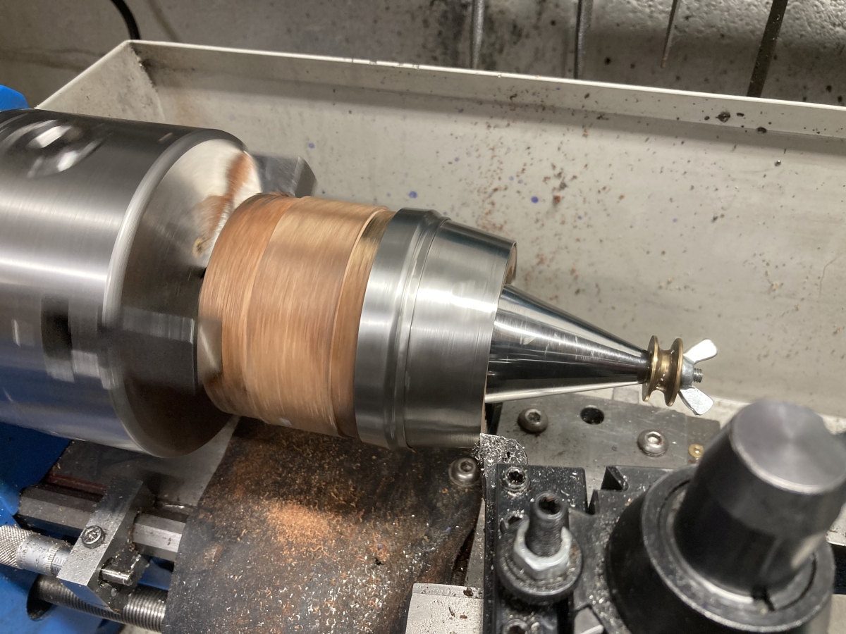
The welded cone was spun over the mandrel using a brass bar in the toolpost of my lathe. I did anneal it a couple of times. It was held in place with pressure from the tailstock on the end of the blank to wedge the conical part tight against the mandrel.
The polishing is totally unnecessary, but I couldn’t help myself!
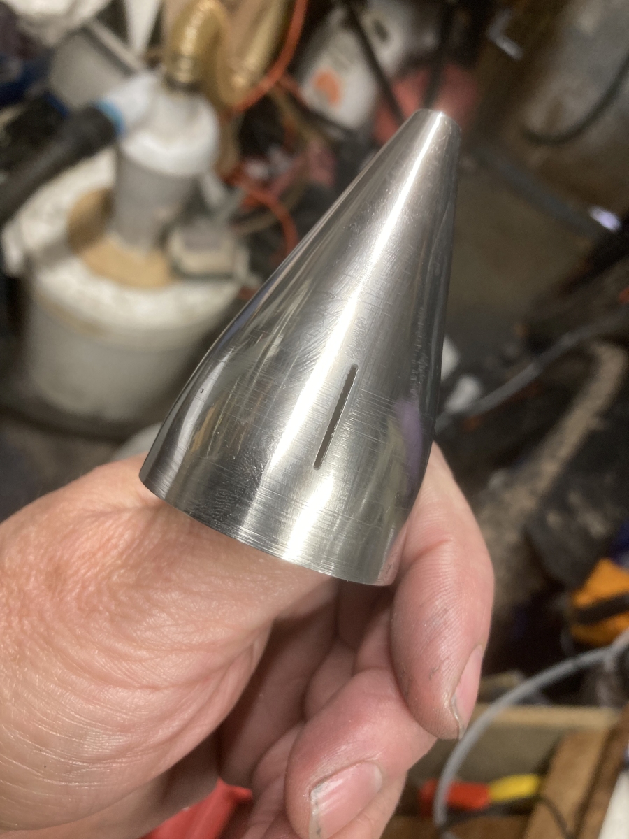
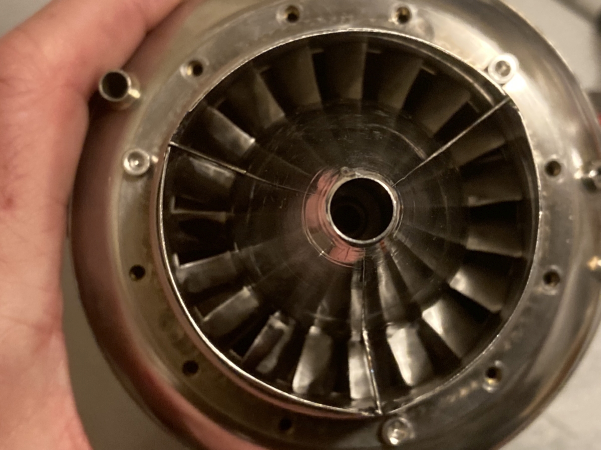
The finished cone outside:

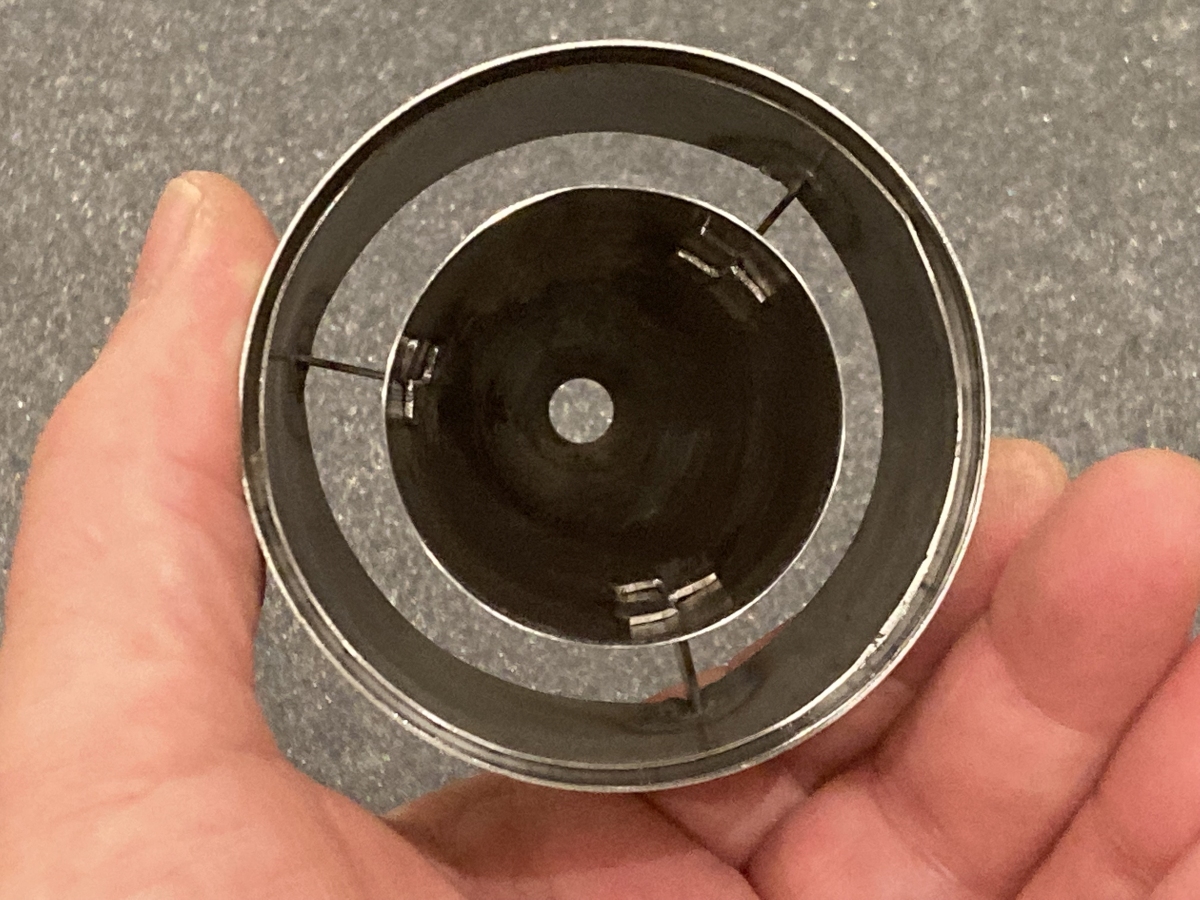
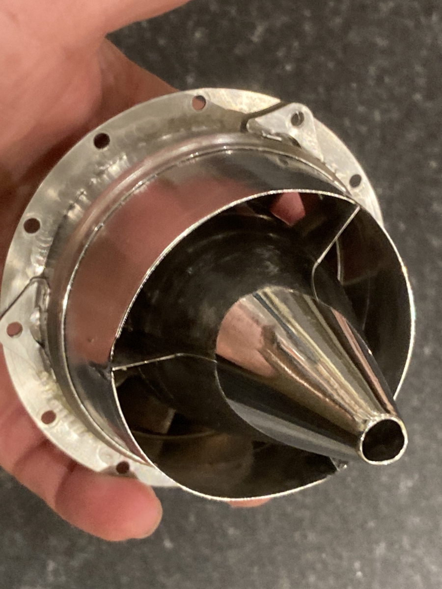
And inside
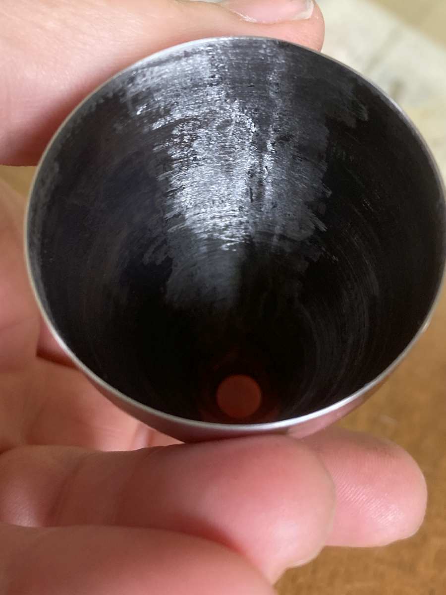
The seam is towards the camera here.
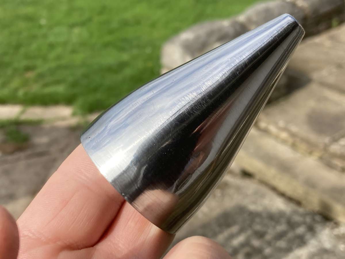
I was VERY pleased with that. I need to cut slits in it to take the support vanes, but I can’t bring myself to do it just yet!
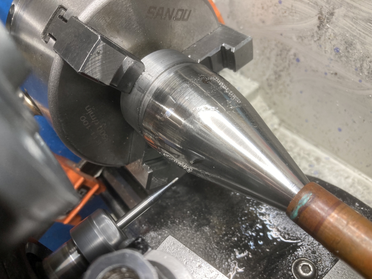
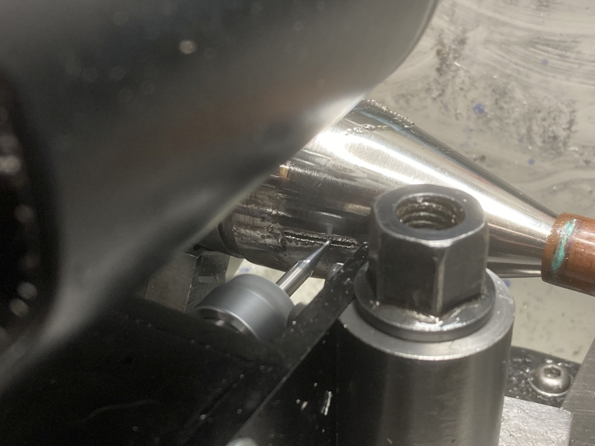
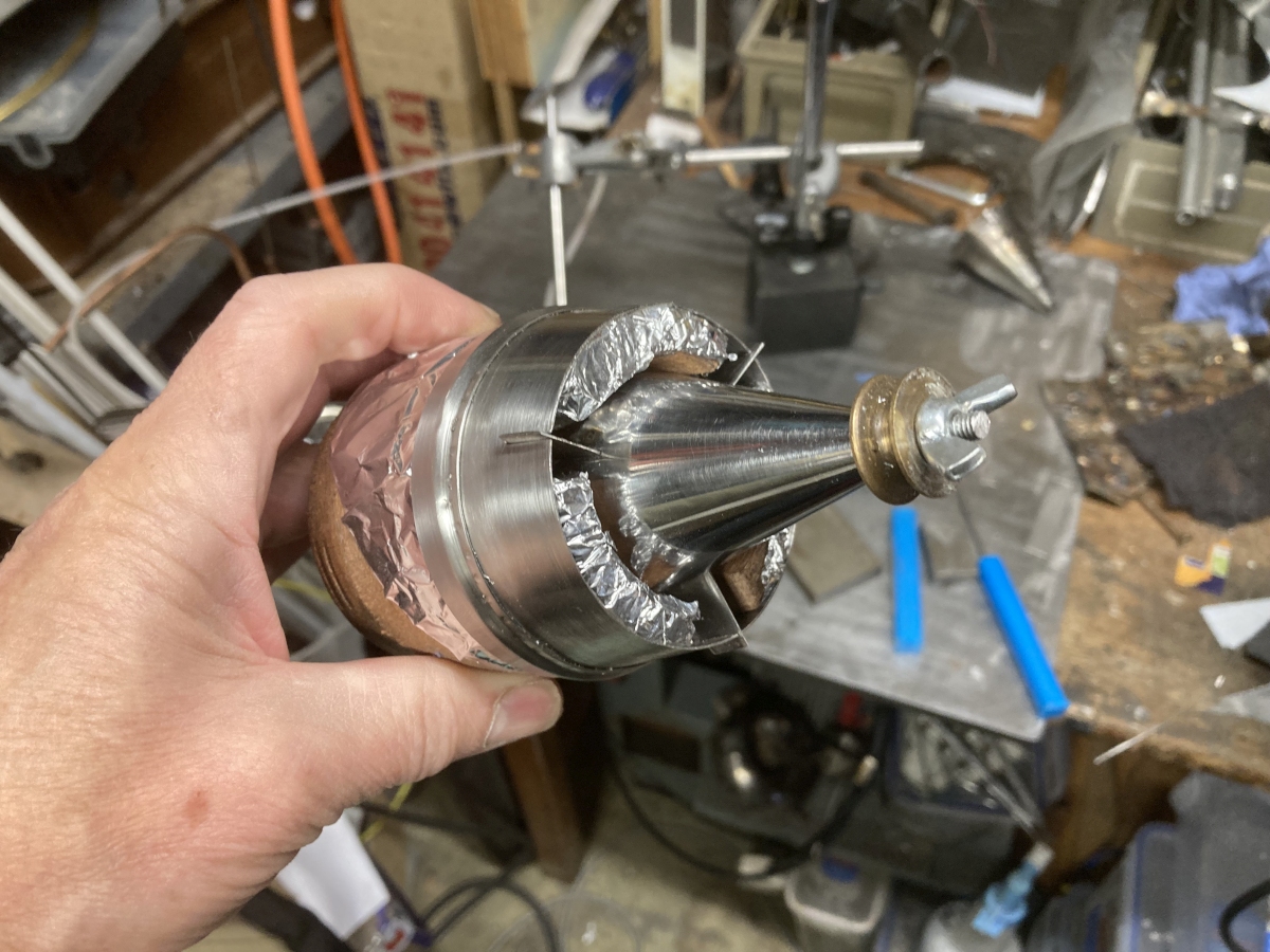
I eventually plucked up the courage to put it back on the mandrel in the lathe and very gingerly used a 1mm diameter end-mill to cut the three slots for the support vanes. (The cone is being pressed onto the mandrel by the length of copper pipe over the tailstock centre.)
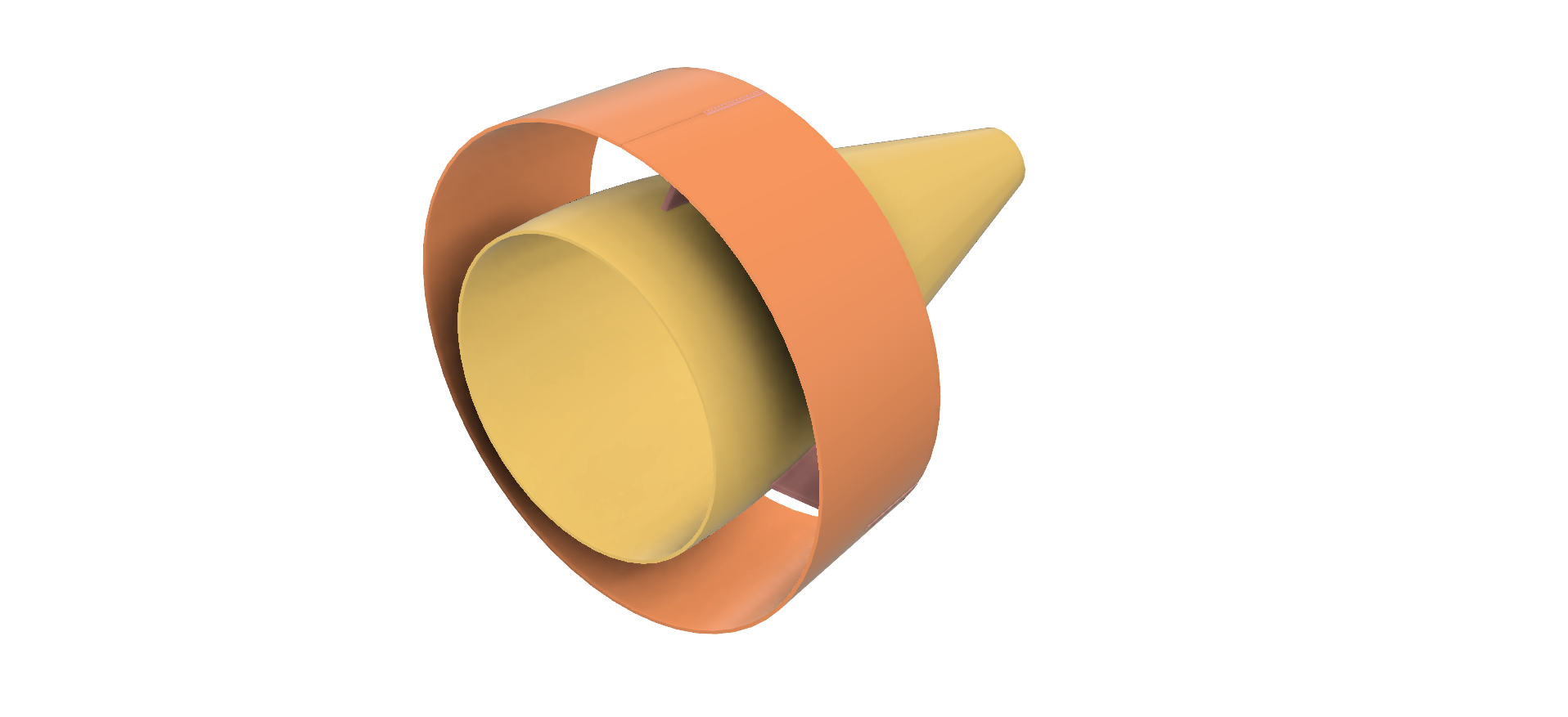
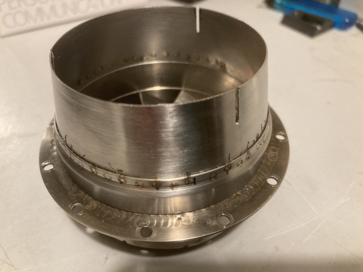
The inside diameter of the outer cone is made to match the inside diameter of the NGV, so there’s a step between them on the outside as the material thicknesses are different. I welded up a plain ring to fit onto the NGV and used a bearing tool to swage it down at an angle until it matched the shape of the outer cone.
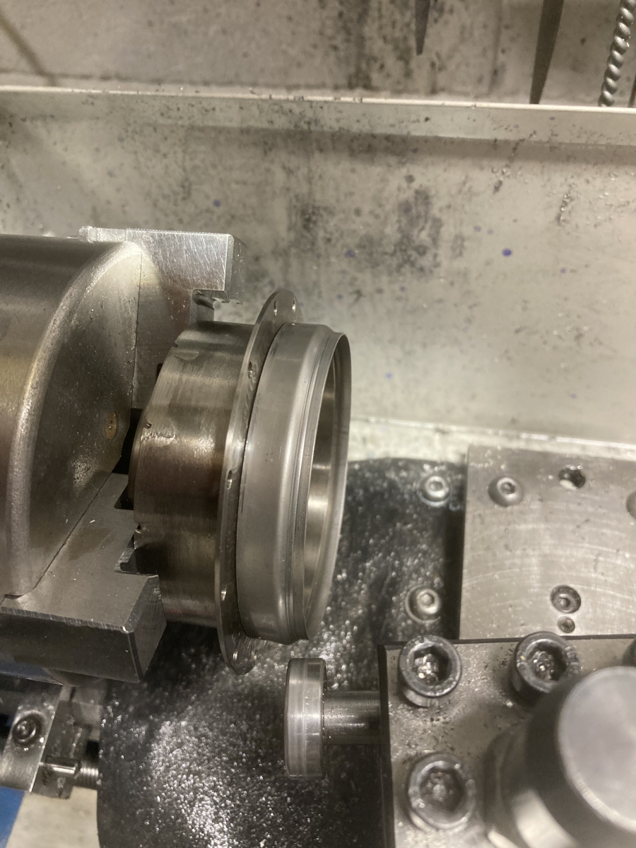
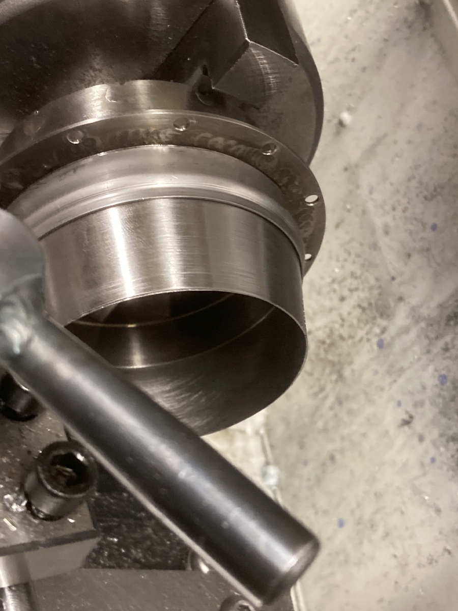
For better or worse, I followed the book’s suggestion to fit the support vanes into slots in the outer cone and weld them on the outside. After cutting the slots (1mm end mill again) the outer cone and mounting ring were spot welded together (the tips need a clean!)
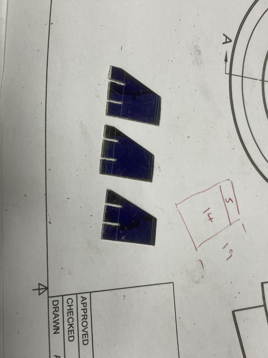
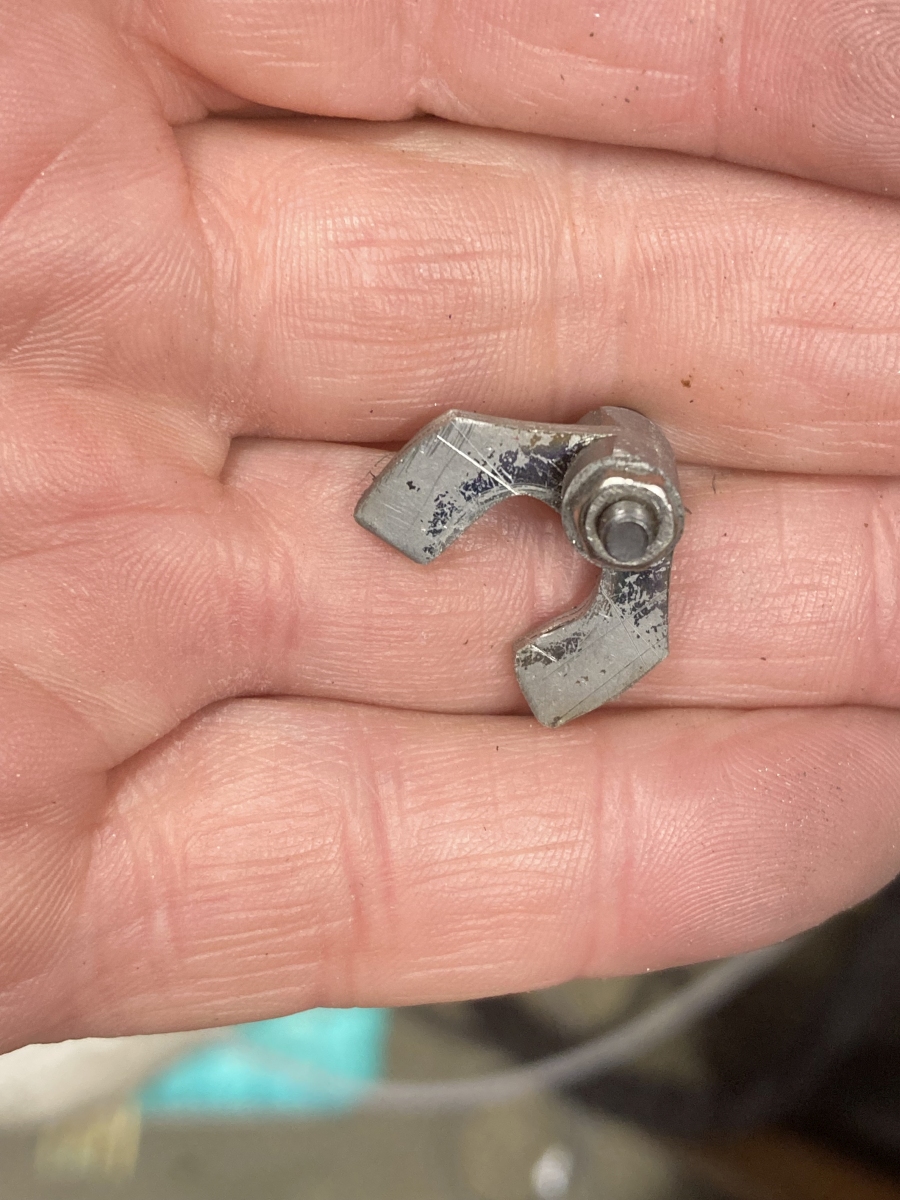
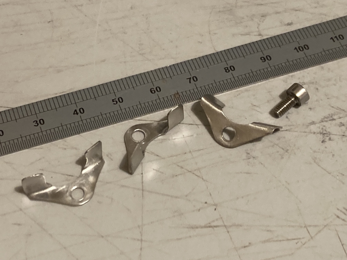
The support vanes are 0.9mm 316 stainless with tabs on the inside ends for spot welding to the inner cone
I modified the wooden mandrel I’d made to form the outer cone to hold everything concentric for welding together. I’d hoped that by cutting the wood away local to the welds and covering the remaining wood in foil that it would survive long enough to get a few tacks in place, at least.
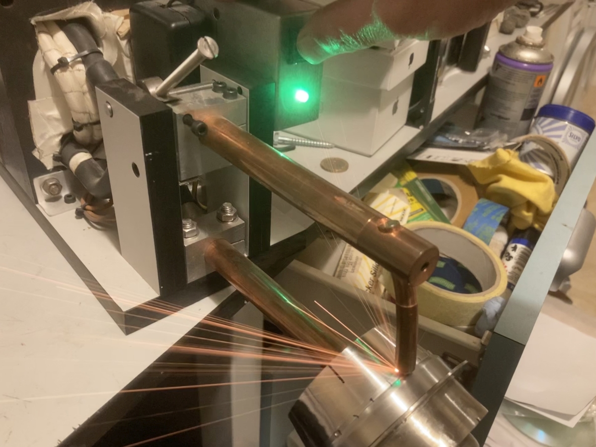
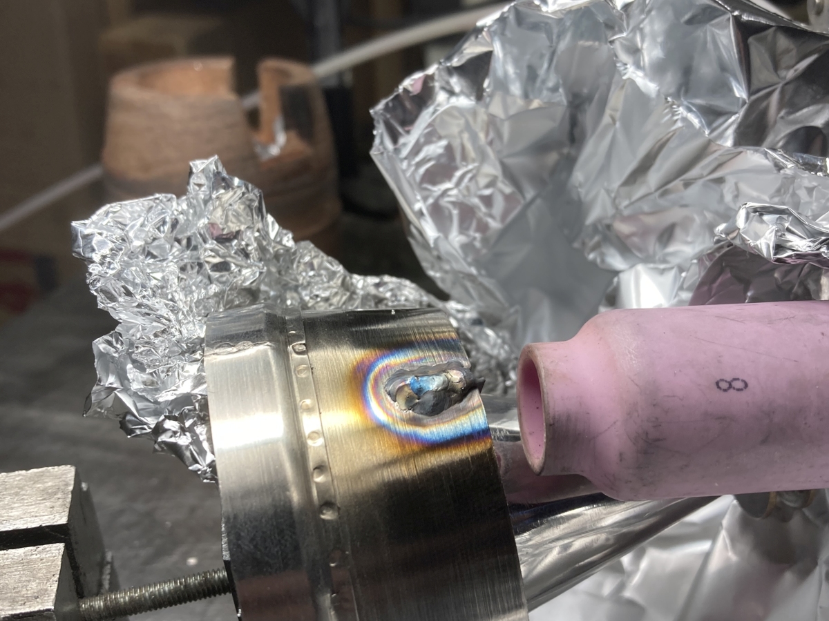
It just about did, but I had to take it off the former to weld… Which was really tricky! The vane is 0.9mm, and the cone is 0.5mm. I thought I would be able to melt the excess length of the vane into the cone. It’s lucky I had a practice first, because I burned the cone away big-style whenever I tried that. The only thing that worked for me was to try and make a tiny fillet weld between the cone and each side of the excess length of vane. I ended up using pulsed DC at 33A, 30% background, 30 Hz and 30% duty (per one of Jody’s ‘welding tips and tricks’ videos on youtube).
This is as good as it got (the gas lens is to purge the inside of the cone – it worked very well, again).
I scraped most of the ugly off, very, very carefully in the lathe.
Part way through, I found that one side of one of the welds wasn’t properly fused, so I put it back on the welding bench to touch it up, and promptly blew a hole through it! I must be improving, because I managed to fill it in again without creating too much mess.
It was nicely concentric with the turbine wheel, but had pulled out of shape around the welds – putting it back on the mandrel shows that it was the ends near the welds that have sprung out; the main curved parts are still OK. I can’t see it being of very much consequence, but we’ll see… If there is a ‘next time’ I would make up an aluminium mandrel (instead of the wooden one) that could be used as a backer when welding.
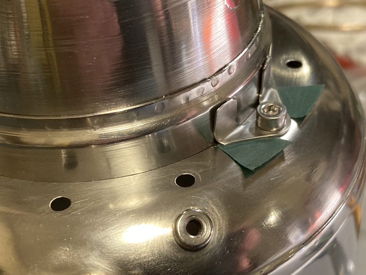
I made some fiddly little mounting brackets to pick up the NGV securing screws:
They were bolted temporarily to the rear of the casing to line them up while they were spot welded to the mounting ring (tape for a bit of clearance).
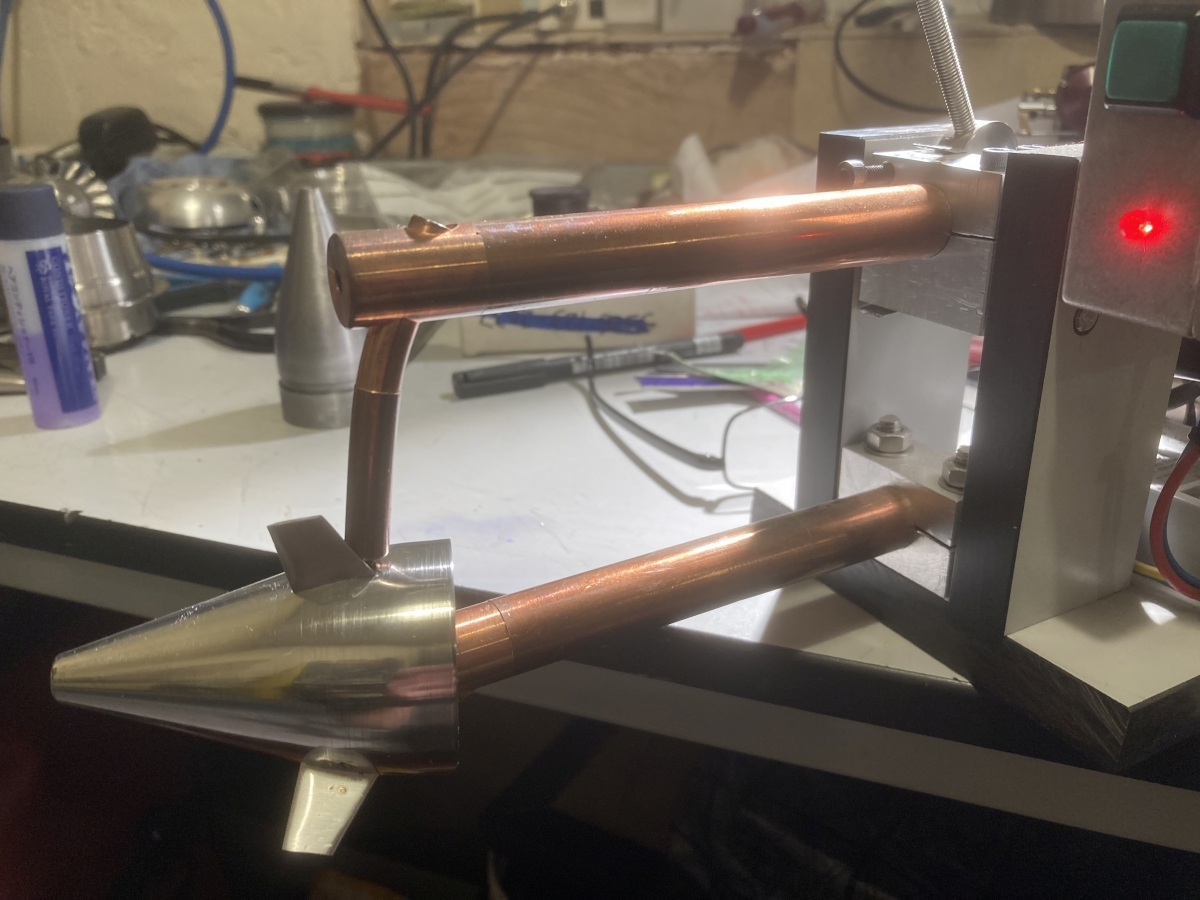
Done!
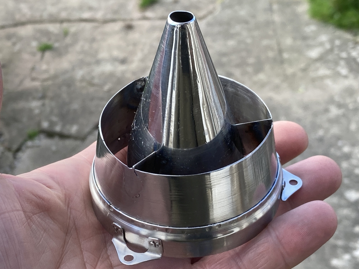
What a fiddly, nerve racking part!
(Dunno why I polished it – it’ll be a blackened mess the first time I try and light the engine.)